Boost converter cannot handle the load within the specifications with audio noise emission.

Thread Starter

boromyr

Joined Nov 26, 2023
24
I am using the TPS61089 for the first time, I am designing the circuit using the dedicated online tool webench but I am getting results well below expectations when using higher loads, the output voltage drops drastically and the device starts emitting audible noise.

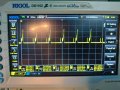
The power supply comes from a 3.7V lithium battery and the output voltage is set to 12V. The device should be able to provide up to 18W, but when I try to add a load of 17ohm (4 resistors of 68 in parallel) the voltage drops to 4/5V and a buzzing noise is perfectly audible during the voltage drop. What could be causing this anomalous behavior?

Attached is the circuit created with the values extracted from webench.

1742680785455.png
 
Place a 0.047 ohm shunt (or two 0.1 ohms parallel) in series with 6u8 coil and measure its voltage drop to check whether current is nice triangular.
There is a possibility the overcurrent protection is periodically activated.
 
Last edited:

Thread Starter

boromyr

Joined Nov 26, 2023
24
This is the waveform at the ends of a 1Ω resistor in series with the inductor, far from being triangular. I can't find the ones that are 0.1 anymore.

The inductor has a slightly lower than expected saturation current, 7.3A, the model is SMS0650-6R8MT.
The layout is as similar as possible to that of the datasheet, I only used R and C 0805.
 

Attachments

ronsimpson

Joined Oct 7, 2019
4,647
The inductor saturates at 7.3A but the IC current limits set at 10A. (100k resistor)
1742684954581.png
One ohm current sense resistor, has too much voltage across it.
 
Last edited:

Thread Starter

boromyr

Joined Nov 26, 2023
24
I also tried using two inductors in parallel to make sure it wasn't a saturation problem, I know it's not actually a good idea but it's just for a test. In theory, for 1A of current there should only be 4.8A of switching current with my current parameters.
 

ronsimpson

Joined Oct 7, 2019
4,647
1A @ 12V = 12W out DC
3.7A @ 3.7V = 12W in DC
I did not look to see if you are running Continuous or Discontinuous.
Of the top of my head I think the peak current is higher than 4.8A.
 
Last edited:

Thread Starter

boromyr

Joined Nov 26, 2023
24
As Michal said, 1Ω is too much, so I bought resistors of 0.1Ω to be able to measure with 0.05Ω.

I also tried to double the saturation current to 14A with two inductors in parallel, but there wasn't much change, even though the inductance value decreased and therefore the initial parameters changed, but still within the device specifications.
 

schmitt trigger

Joined Jul 12, 2010
2,027
Putting two inductors in parallel will halve the inductance, meaning that the inductor current will go deeper into DCM mode.
The inductor won’t suffer, the switching device inside the IC is the one that will. You’ll hit the peak current limit sooner.
 

Thread Starter

boromyr

Joined Nov 26, 2023
24
Even with only one inductor, with a load of 17Ω, 700mA should come out of the boost with a current in the inductor of 4.4A, well below the saturation of the single inductor, which in my case is 7A.
1742815483212.png
 

ronsimpson

Joined Oct 7, 2019
4,647
Have you tried starting the PWM with no load then applying the load? During startup the current is very high. You have the IC set to current limit at 10A.
OR
Change the CL resistor from 100k to 150k or 200k. Get the current limit under 7A.

Here is the current in the MOSFET of a similar boost power supply. See what happens at startup.
1742827040815.png
 
Last edited:

Thread Starter

boromyr

Joined Nov 26, 2023
24
Great suggestion, I will try to lower the current limit.

I always start without load, and then apply it, even if the device has a 4ms soft start. Furthermore, at startup even the 1000μF capacitor is sufficient to check the problem, in fact at startup the acoustic noise can be heard for half a second.
 

Thread Starter

boromyr

Joined Nov 26, 2023
24
1743365670026.jpeg
Inductive current with a load of 17Ω measured using the low resistance of a series jumper cable.
1743365789027.jpeg
Zoom of the previous image
1743365831215.jpeg
Voltage on pin SW
 
Top