 Facebook
 Google
 GitHub
 Linkedin
Hello everyone,
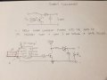
I am trying to build a boost converter using IR2301 gate driver IC. I already built a buck converter which was successful and works great. However, boost converter is the one that I can not get to work. I am only using low side output from the driver. I am really struggling to get the right pin connections. Below you can see the diagram for driving low/high side and my attempt to drive as in a boost converter.
I am trying to build a boost converter using IR2301 gate driver IC. I already built a buck converter which was successful and works great. However, boost converter is the one that I can not get to work. I am only using low side output from the driver. I am really struggling to get the right pin connections. Below you can see the diagram for driving low/high side and my attempt to drive as in a boost converter.
Attachments
-
 145.2 KB Views: 20
 -
 100.1 KB Views: 20


