Boost converter (10MHz switching frequency)

Thread Starter

treek0

Joined Mar 31, 2015
8
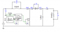
Can anyone help me with constructing a boost converter circuit with the following specs?

Input voltage range: 24 to 48V
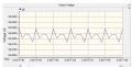
Output voltage: 60V
Output Power: 240W
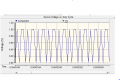
Inductor current Ripple: 10% of Load current
Capacitor voltage ripple: 10mVp-p
Switching frequency: 10MHz (Use MOSFET Switch)

Thank you :)
 

crutschow

Joined Mar 14, 2008
34,408
A 10 MHz switching frequency for a boost converter is an unusually high frequency and it will be quite difficult to get good efficiency at that frequency and power level.
Why such a high frequency?
 

Thread Starter

treek0

Joined Mar 31, 2015
8
I know! Those specifications were assigned to me. I'm having a difficult time trying to implement it. It is possible though, right?
 

Alec_t

Joined Sep 17, 2013
14,312
Welcome to AAC!
Since this is your homework, you need to tell us what approach you've considered/tried so far.
 

Papabravo

Joined Feb 24, 2006
21,225
I know! Those specifications were assigned to me. I'm having a difficult time trying to implement it. It is possible though, right?
Not necessarily. We won't know if it is possible until we try to design something. Did you have a controller in mind that will work at 10 MHz. I don't think a 555 can work at that frequency.

Q: If the output power is 240 watts and the conversion efficiency is 80%, how much input power will be required?
2nd Q: Once you know the input power, how much current will be required from the 24V supply?
 
Last edited:

takao21203

Joined Apr 28, 2012
3,702
Not necessarily. We won't know if it is possible until we try to design something. Did you have a controller in mind that will work at 10 MHz. I don't think a 555 can work at that frequency.

Q: If the output power is 240 watts and the conversion efficiency is 80%, how much input power will be required?
2nd Q: Once you know the input power, how much current will be required from the 24V supply?
Oh God, NE555 at 10 MHz, not in your wildest dreams. It will be aching at 100 Khz.

Sure a 10 Mhz converter with hundreds of Watts, you can get the components from just any distributor or small seller, bread board it and so on.

Even 1 MHz is quite tricky.

10 MHz, a piece of cable, makes a nice Antenna, and with 200 Watts it will transmit happily.

We arent even talking about the inductor (air coil?), or the capacitors.

Sure you dont yet know about the Short Wave phenomena, special HF components, but have been assigned a 200W 10 MHz converter.

You do something wrong and during testing it will give 600 volts, you probably dont even need to touch it...
Or you touch it with a screwdriver and that will radiate off so much energy the whole thing will explode instantly.
 

Alec_t

Joined Sep 17, 2013
14,312
Those specifications were assigned to me
Unless you have been tasked with proving that the 10MHz is not practicable I would ask for the assignment to be modified to have a lower switching frequency.
 

Thread Starter

treek0

Joined Mar 31, 2015
8
Hello

Thanks for the feedback. Not too experienced with constructing circuitry. This is the most intricate project ever assigned to me so please bear with me.

I have calculated and tried building and simulating the circuit using PSCAD with an input voltage of 24V:
Inductor = 3.6uH
Capacitance = 24uF
Duty cycle = 0.6

Simulation results are attached and are not looking promising

Thank you
 

Attachments

Thread Starter

treek0

Joined Mar 31, 2015
8
I will try and ask for a new switching frequency though I doubt it will change. Will a microcontroller handle the 10MHz?
 

Papabravo

Joined Feb 24, 2006
21,225
One of the problems you are going to have is switching the gate of the power device. I don't know if you are aware of this but many devices look like big capacitors. Charging and discharging the gate of an MOS power device quickly will not be easy.

The next problem you are going to have is finding a core to make the inductor that will not saturate.

These are both tall orders.

Why is your supervisor making you run a marathon before you learn to crawl or walk?
 

MrAl

Joined Jun 17, 2014
11,459
Hello there,

Are you sure he didnt say 10kHz instead?

10MHz brings in too many problems, not only with the MOSFET switching (which 100kHz is more common) but also with the layout and inductor choice. Skin effect is going to swamp the whole mess. Also, 3.6uH sounds way too big for 10Mhz, maybe 0.36uH, maybe.

Do you have to actually build this thing or is this just a theoretical exercise?
 

Thread Starter

treek0

Joined Mar 31, 2015
8
Hi. I have to build it, unfortunately. Most of the other students with different supervisors have gotten 500khz.

The students in my supervisor's group have frequencies up to 20mhz!

As for the component values, I have calculated them using the relevant equations.
 

Papabravo

Joined Feb 24, 2006
21,225
Maybe the whole idea of the exercise is to see how you react to complete failure. If you're from a culture where you are supposed to succeed at everything it could be an eye opening experience for you. Keep plugging away and good luck.
 

MrAl

Joined Jun 17, 2014
11,459
Hi. I have to build it, unfortunately. Most of the other students with different supervisors have gotten 500khz.

The students in my supervisor's group have frequencies up to 20mhz!

As for the component values, I have calculated them using the relevant equations.
Hi,

Ok good. Did you ever build a converter before at any frequency?

I suggested a lower value inductor because it's good to stay as low as possible and still meet any ripple specs.
At 50Hz, you can get away with 50uH, so at 500kHz, maybe 5uH, and at 5MHz then 0.5uH, so that's why i suggested lower unless of course you have some very tight specs to catch up with.

If you are really going to build this, then my only other suggesting would be to keep all trace runs as short as possible, because at 10MHz impedances are everywhere in every trace that will work against the efficiency. This means surface mount components are probably a must because with those parts you can get them right next to each other most of the time.

Good luck with it :)
 
Top