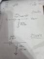
As has been stated already, you almost certainly have a short because unless proven otherwise, the negative rail is probably common between input and output.
isolation when transferring power is obtained by using transformer.
that means you take DC, convert it to AC, then feed it to a transformer. the secondary (or secondaries) can be isolated. then you can rectify, filter and regulate the output(s) to your liking.
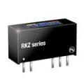
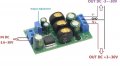
when handling low power, this is usually not worth it, one can get small and low cost DCDC converter module that has it all - isolation, single or dual output etc. they usually look like this:
there are also units for more power, though they tend to become more expensive rather quickly and DIY may be viable option.
one possibility (probably quickest) is to use DC/AC inverter, then connect regular bench PSU with dual outputs.
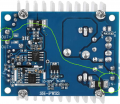
beware of advertisement that cannot be backed up. for example here is an "isolated" boost converter. probably it works nicely...
the real problem is that input and output are not isolated - there is an obvious low resistance path between input and output... it is not a direct short but 0.010 Ohm is pretty close to it.
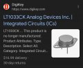
There ARE isolated power modules available. The standard product that I designed years ago uses one that still comes from DIGIKEY to invert the 5 volt supply to power small solid-state LASER modules.
The caution is to always deal with an honest supplier that is truthful about all of the product details. And that understands those details about the products they sell.
There are dual output power modules available and it might cost less to get adual voltage(positive and negative) supply yjan two separate supplies. There are also tracking supplies so that the two voltages will be the same offset from zero volts. Sometimes that is important, sometimes not.
OK, no way to beat the cheap used wall warts on price ! !
BUT if at the thrift store you are able to get a higher voltage wall art of the older type that has a transformer inside, you may be in luck. If that 24 or 30 volt wart can be carefully cracked open you can rescue the transformer, which is usually the expensive part of an isolated supply, , and if that transformer has a center tapped secondary then you can build a split supply that is isolated , and even regulated, AND does not require the frequently replacing of the batteries. AND it might even be capable of more power.
this is an XY problem. TS is looking for making something with parts he has, with limited understanding on how those parts work. the problem may be solved, potentially easier and in a different way if he would just explain what is it that he really needs to do. i' have been doing this for long enough time to know that there are very few loads that require +/-30V, and way fewer that need 250mA. also it is unclear if this has to be powered by 12VDC or if it is possible to use something else... or if this is meant to power specific device... or this is just max specs for something that may change, like a bench PSU.
if you need bench PSU, do yourself a favour and simply buy one. you will not regret it.
you can still make one yourself - making and experimenting with circuits can be very rewarding.
if you need a permanent solution for power some specific load, then get the specs and make PSU for it.
if it only draws 250mA then you do not need 4A.
if you want simplest possible PSU, then transformer,rectifier and caps are needed, transformer need to be chosen carefylly.
if you are not sure that unregulated is ok, add regulator.
if you don't have right transformer, state what you got. almosts any step down transformer rated for 30VA or more can be used. even if it only has single secondary winding, even if it has no taps. even if it is low voltage... that just means you need more of other parts (cheap parts).
for example:
if you need this to be powered by some DC (like 12V) say so. just firm up the specs...
The voltage multipliers shown in post #31 are interesting, BUT I see a challenge because of all of the high value capacitors! Those are not "just filters", but power transfer elements. So the cheap tiny devices are not really suitable. So they will not be the cheapest ones.
The other concern is the actual current capability, since as the voltage is multiplied the current is divided.
That one offered on Amazon seems mighty expensive. For my needs, this may do the job, even thou its not isolated and to over spec'd.
I might get 2 just to see how they perform.
Then, ultimately, with an output capacitor filter
The power supply has to be 12v DC from Lithium and/or lead acid and solar-charged. The circuitry has to be rugged, as it will be finally unmaintained for weeks/months. The load is a number of ultrasonic piezo electric sounders/transducers, so each will be mA and not amps, but the load is capacitive. This is all unknown, ie, the quantity of transducers finally being used, the type of transducer unknown, the actual frequency unknown, the total capacitance unknown, and the actual total current unknown. The transducers will be located in different positions and distances. I have a few different transducers, but how they perform will only be known in the field. So I have to work with what is available and need to accommodate higher outputs than needed. I can always turn the PSU's down, but not up if they are already at the max. I can always bypass circuitry in the field, but not add circuitry. Not forgetting this has to be cost-effective and relatively light to carry.
The components have to be readily available ex stock, and not wait 16 weeks for production. I have even contemplated buying premade modules and unsoldering all the components to install on my pcb. As it's just cheaper than buying the chip on its own.
As you say, making and experimenting with circuits can be very rewarding. Especially when you try to remember your university teaching of about 50 years ago, when vacuum tubes, electron tubes, thermionic valves were still all the rage, not forgetting mercury arc rectifiers.
as already stated several times, you can do that IF the converter is isolated.
but... XL6009 is not isolated: VIN- and VOUT- are already connected internally.
so any time you connect any other power rail to it, you are creating short circuit. View attachment 361219
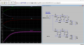
in your case, U26 already has internally shorted IN- and OUT- (2 and 3).
since IN- is tied to "Earth", connecting U26 pin 4 to "Earth" is that short circuit.
You could get that much voltage between Vin minus and Vout positive. At least if the solder side image in post#25 is accurate. BUT one of the SMD resistors might burn.

 Facebook
 Google
 GitHub
 Linkedin