Blown emergency torch ( flashlight) induction charger.

Status
Not open for further replies.

Thread Starter

Harrygrower

Joined Jun 17, 2014
14
At the outset I must admit to having a very limited electronics knowledge so please excuse if I get things wrong.

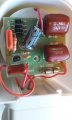
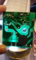
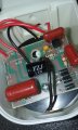
I have umber of purchased a number of rechargeable torches where the chargers have failed. The torches sit in a holder where there is an induction coil which charges the torch. In the event of a power failure the torch will come on, and it will also come on automatically if removed from the base. Unfortunately, the charger keeps blowing. Opening it shows obvious failure of a capacitor and a resistor, but replacing these with a capacitor (Vishay 2.2nF Polyester Capacitor PET 220 V ac, 400 V dc ±10% 368, MKT368 Series Through Hole ) and a resistor (TE Connectivity CFR50 Series Axial Carbon Film Fixed Resistor 2.4kΩ ±5% 0.5W -1200 → 0ppm/°C) does not fix the charger. I have attached pictures of a good and a failed charger, and would be happy to supply any other detailed information of the components as required.

Just looking at the circuit and the board it does not appear to be too complicated so I am hoping that this can be repaired, thereby giving my an opportunity to learn more about electronics, and also get working chargers.

I appreciate that this may not be sufficient information, but anyone cane assist or point me in the right direction, it would be greatly appreciated.

Sincerely

Barry Gower UK
 

Attachments

Last edited by a moderator:

RichardO

Joined May 4, 2013
2,270
There is not much else to go bad. I am guessing one of the four 1N4007 diodes is bad. You can either test them or just replace all four of them since they are only a few cents (pence?) each.

Note that there may be a solder drop near a lead of one of the diodes. Make sure that you never have these since they can cause a great amount of grief when they eventually dislodge and short something out.
 

DickCappels

Joined Aug 21, 2008
10,152
Note: This looks like a transformerless power supply but given the isolated nature of its output it is more like an offline switching supply.

Taking a guess, check each of the four rectifiers and see whether any are shorted.
http://en-us.fluke.com/training/tra...o-test-diodes-using-a-digital-multimeter.html

Similarly check the J300X transistor for a short.
https://www.electronics-notes.com/articles/test-methods/meters/multimeter-diode-transistor-test.php
If those parts are ok, move on to checking for a shorted capacitor. If all the parts still look good, the problem might be on the load side.
 

LesJones

Joined Jan 8, 2017
4,174
Can you post a picture of the etch side of the board so that we can trace out the schematic so we understand where the failed resitor and capacitor are. Also have you checked that the fault has not blown the glass wire ended fuse on the AC input ?

Les.
 

Thread Starter

Harrygrower

Joined Jun 17, 2014
14
Richardo, DickCaplpels, LesJones,

Sincere thanks for the quick and detailed response. I have attached further pictures showing the charger I have attempted to repair, with the new parts as noted previously.The pictures also show the etch side of the board. Please let me know if there is anything further you need in terms of identifying the components. I have an old analogue multi-meter which I normally just use for testing batteries and the integrity of other things - so Les using this shows the fuse to be good. I do need a new one, so can you suggest anything suitable for my limited application, but which clearly must be able to test the components you are referring to.

Many thanks for your help and your patients.

Barry
 

Attachments

LesJones

Joined Jan 8, 2017
4,174
There is not enough contrast in the picture of the etch side of the board to see the etch clearly so I have not been able to trace the schematic. Possibly illuminating it from the component side might help.

Les.
 

Thread Starter

Harrygrower

Joined Jun 17, 2014
14
Richardo, DickCaplpels, LesJones,

Sincere thanks for the quick and detailed response. I have attached further pictures showing the charger I have attempted to repair, with the new parts as noted previously.The pictures also show the etch side of the board. Please let me know if there is anything further you need in terms of identifying the components. I have an old analogue multi-meter which I normally just use for testing batteries and the integrity of other things - so Les using this shows the fuse to be good. I do need a new one, so can you suggest anything suitable for my limited application, but which clearly must be able to test the components you are referring to.

Many thanks for your help and your patients.

Barry
There is not enough contrast in the picture of the etch side of the board to see the etch clearly so I have not been able to trace the schematic. Possibly illuminating it from the component side might help.

Les.
Thanks Les - I have taken 3 further pictures - One with a light source behind the whole etch from the component side , and then two further images, high-lighting top and bottom. Trust this will give you what you need.
Thanks
 

Attachments

LesJones

Joined Jan 8, 2017
4,174
Hi Barry,
Those new pictures were fine. This is the schematic I traced from the pictures.

schematic060717.jpg

The three connections marked "transistor ?" are probably an NPN transistor. I think the bottom connection is the emitter. The middle connection the collector and the top connection the base. Can you read a part number on the device I think is a transistor ? We may be able to find a data sheet for it. I suspect that it was thefirst item to fail (Collector emitter short.) and this caused the resistor and capacitor to fail.

Les.
 

Thread Starter

Harrygrower

Joined Jun 17, 2014
14
Thanks Les - I have attached some pictures showing the details of the transistor. The markings are 13001 and below it looks like 80.D331 ( this could be 80.0331). The etch shows the same number . This yellow has some small markings, which look like 104 and this is on the etch as well.

Thanks for this

Barry
 

Attachments

DickCappels

Joined Aug 21, 2008
10,152
Nice schematic, LesJones.

The transistor is probably and MJ13001 which is popular in cheap phone chargers. The center pin is the collector. The emitter is the same place you would find it on a 2N3904.

From the location of the failed components the transistor is shorted. From the schematic without a load the collector voltage can become very large. A poor design at best.

Datasheet:
www.datasheetspdf.com/datasheet/MJ13001.html
 

Thread Starter

Harrygrower

Joined Jun 17, 2014
14
Thank you for your comments DickCappels. I will be looking at buying transistors first thing tomorrow. Re your comments on poor design- couldn't agree more, hence blowing so many ( I do need this for my elderly mother though).

Have you any thoughts on which transistor to purchase -RS give a number of options http://uk.rs-online.com/web/c/?searchTerm=transistors++high+voltage&sra=oss&r=t , and whether there are any modifications I can make to any of the components which would improve the design.

Sincere thanks to all for time and interest.

Barry
 

DickCappels

Joined Aug 21, 2008
10,152
Your search turned up three '13003 transistors. They are similar to the MJ13001 but with higher collector-to-emitter voltages. Since too high of a voltage on the collector is what probably killed the original part using the '13003 might solve the problem. Any of those three should work fine, though I am partial to Diodes Inc.

It is a good idea to only turn the charger on after the flashlight is in the charging position and to turn it off before removing the flashlight. That might prevent the collector voltage from getting too high because there will always be a load on the charger while operating.
 

Thread Starter

Harrygrower

Joined Jun 17, 2014
14
I was thinking the same !! Actually, since I have about 7 of these failed chargers ( don't ask - family friends on my recommendation ) I will be able to use some of them at least. I do hope that this will work, as it is an otherwise good product, and most useful, especially for the elderly.
 

Thread Starter

Harrygrower

Joined Jun 17, 2014
14
Here is the latest up date and I am afraid it still is not working.
  1. I have replaced the transistor as per the images below ( I assume that the soldering is OK, but not sure if/how to check this - do you put a meter across the terminals and if so across which?)
  2. Checked that the on board fuse is good
  3. Checked the plug fuse is good.
I realise that the pictures don't show too much. However, the wire on the underside did come off, and although I believe I have soldered it back in the correct position, affirmation of this would be good.

Otherwise, any other suggestions ( else I will just have to try and sell 99 transistors!)

Out of interest, if all else fails, would it be possible and realistic to de-solder the whole board and replace the components as identified in Les' schematic?

Many thanks
 

Attachments

On a good charger. with a load connected (charging). the following I think would be useful:

1) DC Voltage across 4.7 uF cap
a) Fitting a ZNR (surge suppressor),TVZ here would be a good idea.
b) What's your mains voltage and frequency?

2) AC voltage across 560 nF capacitor
a) would give an idea of the current.

3) AC voltage across L1, L2 (The induction coil)
 

Tonyr1084

Joined Sep 24, 2015
7,853
Note that there may be a solder drop near a lead of one of the diodes. Make sure that you never have these since they can cause a great amount of grief when they eventually dislodge and short something out.
My thoughts as well on the solder ball. They can float around and short something, causing a cascading failure. Free stuff is free stuff, and sometimes it's easy to get it up and running again. But I'm thinking these are probably so cheap that it's easier and more cost effective to just replace them. Someone also mentioned "Mains Voltage", which is what I was wondering about the first time I saw the circuit. I'd be concerned when messing with such stuff, so be careful. We would hate to lose a new member.

It is a good idea to only turn the charger on after the flashlight is in the charging position and to turn it off before removing the flashlight. That might prevent the collector voltage from getting too high because there will always be a load on the charger while operating.
Dick: The way this is designed to work is the unit is plugged into the outlet with the torch (flash light) sitting in the cradle. IF there's a power failure the flash light automatically comes on. Sort of an emergency light. I have a few of these as well. ALSO, if you lift the torch from the cradle it comes on immediately (again, by design). So switching it on and off before or after use is not practical in this case.

I've never opened any of mine. Looking at your pictures I'd be afraid to open mine. Not as if I fear electronics, no. I fear poor design and craftsmanship.

One thing I've learned over the years is to fully diagnose the problem BEFORE you start buying (or replacing) parts. With "Cascading Failure" if something goes it can drag several other things down with it. It's possible (I'm not the expert here, but it's possible) that one or more diodes may have gone out as well. It's possible that may be where the cascade began. It could be a faulty coil causing too much current to draw. It could be a lot of things. Short of replacing EVERY component I don't think you're going to get it up and running again.

Someone said they think the transistor is in backwards. I thought that too when I looked at the silk screen (the white paint on the board). But when I looked back at your early pictures I saw that was how the original transistor was installed. Don't know why the silk screening would be wrong, but I've seen that many times before in my 30+ years as an electronics inspector.
 

DickCappels

Joined Aug 21, 2008
10,152
If you have doubts about the orientation of the transistor you can check the circuit board against LesJones's schematic in post #8 by seeing which components connect to which leads. For example, the emitter connects to two capacitors and a 2.4k resistor (red-yellow-red-gold (or silver)).

@Tonyr1084 : If it cannot be turned off and on then we are stuck with only thehope that the increased collector voltage rating is enough keep the failure from reoccurring.
 
Status
Not open for further replies.
Top