Blinky with PICKit 2 and Velleman Dev Board

Thread Starter

David_Baratheon

Joined Feb 10, 2012
285
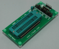
Hi everyone, I am attempting to program a PIC12C509A that has been plugged into the 8 pin IC Socket on the Velleman board. I am attempted to both program and power the PIC using a PICKit 2 since I dont have the 15V adapted or a serial port on my laptop. I am having a bit of trouble getting it going so just wondered if I could get a bit of help? Here is a picture of my equipment. I am using MPLAB X as my IDE.


Here is my code:


Code:
;*******************************************************************************
; Processor Inclusion
;
; TODO Step #1 Open the task list under Window > Tasks.  Include your
; device .inc file - e.g. #include <device_name>.inc.  Available
; include files are in C:\Program Files\Microchip\MPLABX\mpasmx
; assuming the default installation path for MPLAB X.  You may manually find
; the appropriate include file for your device here and include it, or
; simply copy the include generated by the configuration bits
; generator (see Step #2).
;
;*******************************************************************************

; TODO INSERT INCLUDE CODE HERE
#include "P12C509A.inc"
;*******************************************************************************
;
; TODO Step #2 - Configuration Word Setup
;
; The 'CONFIG' directive is used to embed the configuration word within the
; .asm file. MPLAB X requires users to embed their configuration words
; into source code.  See the device datasheet for additional information
; on configuration word settings.  Device configuration bits descriptions
; are in C:\Program Files\Microchip\MPLABX\mpasmx\P<device_name>.inc
; (may change depending on your MPLAB X installation directory).
;
; MPLAB X has a feature which generates configuration bits source code.  Go to
; Window > PIC Memory Views > Configuration Bits.  Configure each field as
; needed and select 'Generate Source Code to Output'.  The resulting code which
; appears in the 'Output Window' > 'Config Bits Source' tab may be copied
; below.
;
;*******************************************************************************

; TODO INSERT CONFIG HERE
__CONFIG _OSC_IntRC & _WDT_ON & _CP_OFF & _MCLRE_ON
;*******************************************************************************
;
; TODO Step #3 - Variable Definitions
;
; Refer to datasheet for available data memory (RAM) organization assuming
; relocatible code organization (which is an option in project
; properties > mpasm (Global Options)).  Absolute mode generally should
; be used sparingly.
;
; Example of using GPR Uninitialized Data
;
;   GPR_VAR        UDATA
;   MYVAR1         RES        1      ; User variable linker places
;   MYVAR2         RES        1      ; User variable linker places
;   MYVAR3         RES        1      ; User variable linker places
;
;   ; Example of using Access Uninitialized Data Section (when available)
;   ; The variables for the context saving in the device datasheet may need
;   ; memory reserved here.
;   INT_VAR        UDATA_ACS
;   W_TEMP         RES        1      ; w register for context saving (ACCESS)
;   STATUS_TEMP    RES        1      ; status used for context saving
;   BSR_TEMP       RES        1      ; bank select used for ISR context saving
;
;*******************************************************************************

; TODO PLACE VARIABLE DEFINITIONS GO HERE
_blink equ 0x020

;*******************************************************************************
; Reset Vector
;*******************************************************************************

;RES_VECT  CODE    0x0000            ; processor reset vector
;   GOTO    START                   ; go to beginning of program

;*******************************************************************************
; TODO Step #4 - Interrupt Service Routines
;
; There are a few different ways to structure interrupt routines in the 8
; bit device families.  On PIC18's the high priority and low priority
; interrupts are located at 0x0008 and 0x0018, respectively.  On PIC16's and
; lower the interrupt is at 0x0004.  Between device families there is subtle
; variation in the both the hardware supporting the ISR (for restoring
; interrupt context) as well as the software used to restore the context
; (without corrupting the STATUS bits).
;
; General formats are shown below in relocatible format.
;
;------------------------------PIC16's and below--------------------------------
;
; ISR       CODE    0x0004           ; interrupt vector location
;
;     <Search the device datasheet for 'context' and copy interrupt
;     context saving code here.  Older devices need context saving code,
;     but newer devices like the 16F#### don't need context saving code.>
;
;     RETFIE
;
;----------------------------------PIC18's--------------------------------------
;
; ISRHV     CODE    0x0008
;     GOTO    HIGH_ISR
; ISRLV     CODE    0x0018
;     GOTO    LOW_ISR
;
; ISRH      CODE                     ; let linker place high ISR routine
; HIGH_ISR
;     <Insert High Priority ISR Here - no SW context saving>
;     RETFIE  FAST
;
; ISRL      CODE                     ; let linker place low ISR routine
; LOW_ISR
;       <Search the device datasheet for 'context' and copy interrupt
;       context saving code here>
;     RETFIE
;
;*******************************************************************************

; TODO INSERT ISR HERE

;*******************************************************************************
; MAIN PROGRAM
;*******************************************************************************

;MAIN_PROG CODE                      ; let linker place main program

;START

    ; TODO Step #5 - Insert Your Program Here

    MOVLW 0x55                      ; your instructions
    GOTO $                          ; loop forever

END
I am looking to get just enough basic code together so that it will actually run so I can test the hardware setup. What changes do I need to make to my code to make it run?

Also, I have tried to program and power my PIC and Dev board and it is saying "no device detected" so what do I need to do to get this hardware working firstly for programming and secondly for actually running the PIC on the Dev board for testing?
 

jpanhalt

Joined Jan 18, 2008
11,087
Isn't the 12C509A one-time programmable? If so, I suggest getting a 12F509A to practice on and to be sure your program works.

Where's your code? Those are just templates.

Edit: "Device not detected" may be the result of improperly setting your programmer. First be sure you have selected the proper chip in the configure drop-down. Then in the programmer dialog go to settings>power and select power target by programmer and set the proper voltage.

John
 
Last edited:

Thread Starter

David_Baratheon

Joined Feb 10, 2012
285
I used the template to start my code. I have some basic code within the template. Namely a link to the appropriate header file, the config word, and just a simple loop. The idea was just to make a start and then I can start building on my code and implement a blinky program, and finally move on to my intended purpose for the microcontroller.

I hadn't realized they were OTP to be honest. I have a PIC16F84A so I will use that instead. These were just ones I had lying around and so I thought I might aswell use what I have rather than ordering in more.

I do have about 5 of these PIC12C509A chips so its possible for me to use them I guess. I was given them. Now I know why lol.

Still, how do I get the velleman board working for programming and also for running the microcontroller?
 

jpanhalt

Joined Jan 18, 2008
11,087
Did you do the steps I suggested for the programmer in Configure and Programmer drop downs?

Have you gone through any tutorial for Assembly and PIC's? There are plenty of them. Gooligum ( http://www.gooligum.com.au/tutorials.html) and Nigel Goodwin (http://winpicprog.co.uk/pic_tutorial.htm ) are two I can recommend.

Since you appear to want to use relocatable code, at least in some of your examples, then Gooligum is the way to go. I would suggest, however, to start with absolute code. In which case, either tutorial is good. If you are really just beginning, I would recommend Nigel's until you get an LED blinking, but that bias is slight.

John
 

Thread Starter

David_Baratheon

Joined Feb 10, 2012
285
Jpanhalt ok I will go through that to help me develop my code, but what do I need to do from a hardware perspective? Can I program the PIC using the PICKit 2 and Velleman board and can I power it up and utilise the switches and LEDs using the PICKit 2?

Can it be done with my current hardware or should I buy something like this:

http://www.ebay.co.uk/itm/New-PIC-U...al_Components_Supplies_ET&hash=item2eca31e3dd
 
Last edited:

tracecom

Joined Apr 16, 2010
3,944
I have looked at the schematic for the Velleman board, and it looks like you can use it as a programming platform for the PICkit 2. All you need is a 12-15 VDC power source capable of at least 300mA for the Velleman board, and a method to connect the PICkit2 to the correct pins on the Velleman board.
 

jpanhalt

Joined Jan 18, 2008
11,087
1) I have not looked at the Velleman board, so will take tracecom's word for how to use it.
2) Re: eBay item. I do not believe you need that programmer. The PK2 is really a great programmer and has lots of support. You can even use it as a logic analyzer. I do not own one. I do own the PK3, which is similar but cannot be used as a logic analyzer and I/O probe. The PK3 has a fairly weak power supply, and I believe the PK2 is similar. That factor comes into play when doing In Circuit Serial Programming (ICSP, which is a registered TM of Microchip).

General Comment:

There are several ways to program a chip and some terms may be causing confusion. Let me try to sort it out a little for you. For simplicity, consider only the Microchip products that have been mentioned so far, e.g., 12Fxxx, 12F1xxx, 16Fxxx, and 16F1xxx chips. Consider these two choices: 1) Program the chip by itself; and 2) Program the chip while it is in a circuit by accessing specific pins. In the latter case, those pins that are used for programming need to be isolated during programming from the rest of the circuit. Such in-circuit programming is called ICSP by Microchip.

If you look at Microchip's offerings for programmers, you will find devices such as the PicStartII Plus, which is a stand alone programmer. It has a 40-ppin ZIF socket. You attach the programmer to a PC (mine just used a standard serial, 9-pin connector), put the chip in the socket, close the lever, and program. Works great, but what do you do with a chip that doesn't have pins that fit that socket? You can make an adapter board with pins or wires to the appropriate pin locations in the socket. That is basically what the ICSP programmers do.

As a hobbyist, the Microchip ICSP programmers to consider are the PK2, PK3, and ICD3 (more expensive). None of those programmers is designed like the PicStartII Plus with its own socket, but you can buy adapter sockets from Microchip or elsewhere, or make your own. I got mine from Joshua1Systems ( See: http://www.j1sys.com/icsp-adapters/ ). There are other vendors. I found mine on eBay. They come with ZIF sockets for various sizes of chips, Here is what the largest (40-pin) version looks like:
upload_2014-12-24_4-33-55.png

In operation, you must configure the jumpers for the chip you are using, then attach the ICSP programmer to the six pins on the right and program away. It is very much like using a PicStartII Plus. As I mentioned in an earlier post, you must go to programmer> settings>power and select power target by programmer and voltage (for the chips you have mentioned that is 5V). Now, "target" is the term used by Microchip for the chip. In this case, it is just the chip in an adapter board. It may be a bit of a misnomer, but it is still called ICSP.

As an alternative, you can design your working circuit to be programmed using ICSP. That is where the Velleman board comes into play. If you are programming a chip in its operating circuit, not in just an accessory board, then you must decide whether to power the "target" by the circuit or by the programmer. The PK2 and PK3 have very small power supplies. I don't recall the exact specifications, but I believe they are limited to about 30 mA. The ICD3 can supply 100 mA. Thus, if you have a circuit that requires more power than the programmer can supply, you must provide that accessory power or provide isolation so that less power is required. As an example, assume your circuit includes a large LCD display. The backlight for that display may require 30 mA . It would be a little uncertain whether the PK2 could provide the power and program in that circuit; however, you might design your circuit with a jumper for the backlight. If you remove that jumper, then the circuit may only need a few milliamps and can be programmed just fine powered by the programmer.

Now, you ask about powering LED's with your PK2. I don't know how many LED's you are talking about nor their current needs. But clearly, you may well exceed the supply ability of the PK2. That is where powering by the target (e.g., the Velleman board) comes into play.

I hope this early morning (for me) drivel helps.

John

Addendum: On some further reading, I don't believe your PK2 can even program OTP chips, as they require voltages or currents that it cannot supply (http://www.microchip.com/forums/m510026.aspx ).
 

Thread Starter

David_Baratheon

Joined Feb 10, 2012
285
I agree that PICKit 2 is perfect for programming, but I need to somehow connect it to a PIC and also need to test the PIC once it's been programmed. I thought the velleman would enable me to do those two things. I don't want to construct my own for now. The Velleman board doesn't come with a power supply unfortunately.

Is there a quick easy dev board I can insert a PIC into and the PICKit2 onto and then program the chip and test it if it has a few buttons and LEDs?

The reason I thought I could use a Velleman board is because if you look, it has 5 pins, and the 6th pin of the PICKit 2 is just an auxillary pin. As PICs only need 5V I figured I could draw 5V from the PICKit 2 when testing. The board has multiple buttons and LEDs.I thought I could just hook my PICKit 2 onto the 5 pins on the velleman board

As the velleman board has various IC sockets I thought I can just insert my PIC into the relevant socket to program and test it
 

hexreader

Joined Apr 16, 2011
619
You CAN program PIC16F84 with PICkit2 and the Velleman board that you have.

PICkit2 can supply enough power, so you already have everything that you need.

Connect PICkit2 pin 1 to SK3 pin 1 (pin 6 will just hang unconnected - that is OK)

Fit jumpers to JP3 and JP4

Leave the PROG switch in the run position.

PIC16F84A goes into "18P" socket - be sure that pin1 goes to pin1

Hex file attached that will flash all LEDs

Enjoy!
 

Attachments

Last edited:

Thread Starter

David_Baratheon

Joined Feb 10, 2012
285
In googling, I found this thread.

http://forum.allaboutcircuits.com/threads/pickit2-and-velleman-vm111.96917/

It seems that you have been through this before. What have you tried and what have been the results?
The last time I had a go was when we were using PICs in university but it was very new to me at the time. We were given hand built PCBs in the end that could program and run what we had built in class. We didn't touch microchip again for years so now having another go and want to be able to go self sufficiently so once I can use my hardware and upload programs I can start experimenting.

Since then we've used national instruments myrio which are easier to use.
 

Thread Starter

David_Baratheon

Joined Feb 10, 2012
285
You CAN program PIC16F84 with PICkit2 and the Velleman board that you have.

PICkit2 can supply enough power, so you already have everything that you need.

Connect PICkit2 pin 1 to SK3 pin 1 (pin 6 will just hang unconnected - that is OK)

Fit jumpers to JP3 and JP4

Leave the PROG switch in the run position.

PIC16F84A goes into "18P" socket - be sure that pin1 goes to pin1

Hex file attached that will flash all LEDs

Enjoy!
Thanks so much for your help. I'll give that a go and see how I get on. One question. What's the jumpers on jp3 and jp4 for?
 

Thread Starter

David_Baratheon

Joined Feb 10, 2012
285
Guys I've tried uploading that hex file but it says device error, hex file not loaded

Jpanhalt if I can't get this to work I'll prob try your eBay suggestion
 

tracecom

Joined Apr 16, 2010
3,944
Last edited:

jpanhalt

Joined Jan 18, 2008
11,087
You can do ICSP with short jumpers from the PK2 to your device on a perf board. No need to order something off ebay and wait just to trouble shoot this problem. The datasheet shows which pins to use. Ordering a set might be useful for the future, though.

Keep the jumpers short, but practical. I did ICSP with my PicStartII and 6" jumpers. You can also erase the PIC and then do a blank check. If it doesn't read blank there is a problem early on. The programmer will report "erase" , because that is what it thinks it did with Vpp. You need to read it to be sure it is erased.

John
 
Top