Bldc motor driver with 4 hall sensors

JohnSan

Joined Sep 15, 2018
130
Sure.

But each time the drive is powered up, the motor has to 'start' and rotate maybe one full revolution to find where that zero pulse is.

That doesn't fit in with the OPs requirement, as you correctly quoted " ... increased resolution for increased starting/direction change smoothness' .

The controller will not know the rotor / stator position relationship until it has rotated the motor, maybe almost one complete turn.
 

MaxHeadRoom

Joined Jul 18, 2013
30,717
Again, I quote the original required spec !
"For increased resolution for increased starting/direction change smoothness m, robustness, and snappiness"
The quadrature encoder has all those qualities.
I have been using them for 55Yrs now !!
 

nsaspook

Joined Aug 27, 2009
16,370
Sure.

But each time the drive is powered up, the motor has to 'start' and rotate maybe one full revolution to find where that zero pulse is.

That doesn't fit in with the OPs requirement, as you correctly quoted " ... increased resolution for increased starting/direction change smoothness' .

The controller will not know the rotor / stator position relationship until it has rotated the motor, maybe almost one complete turn.
Easy, you set the zero a known small distance from the home position. Mechanical systems have drift that needs to be accounted forward. Trust in sensors needs to be earned by checking, unless you don't care about crashes.

https://youtube.com/shorts/xlD6s_BpNyE?si=BGOaMMC4jPm5P82f

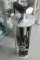
photooriginal-2606511-qJah5.jpg
Encoder position feedback.
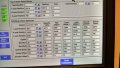
IMG_20190217_142659698_HDR.jpg
Robot teaching screen.

1750010726667.png
 
Last edited:

JohnSan

Joined Sep 15, 2018
130
I'm sorry if I've lost the plot here.

But I thought the OP question - Re: using 4 Hall Effect sensors, was for improving the control of a BLDC MOTOR. He then stated they are designing / building their own.

The IC device he referred to 'mct8316z' (which he wanted to improve upon), is a motor controller which uses 3 Hall Effect devices, in order to control a 3 phase BLDC motor. The Hall Effect devices are embedded in the motor and sre used to sense the rotor position relative to the motor stator windings. The IC then controls the current into the 3 windings to produce torque, to create motor rotation.

We are not talking about speed/position control of some mechanical device that it is attached to!

So, using 4 hall effect sensors implies a motor with 4 windings maybe?
The comment on designing/builing their own was vague here.

To manufacture 3 winding BLDC motors, with 4 hall effect sensors sounds expensive to me.
Or maybe a new type 4 winding BLDC ?
And then creating a new IC chip to control it using 4 Hall Effect devices?

Maybe not.
Just add a resolver, - which is analogue - and it will always give the rotor position relative to stator windings. Every time the power is switched on. No need for referencing. (Well, after thr initial setup commissioning).
Stepper motors use micro-stepping to smooth movement. Maybe that could be applied here?

As I read it, most of the other comments in this thread are referring to encoders on a motor used within some mechanical system.
Which is completley different to the original question:- controlling the current in the motor to produce a smoother torque profile. Which cannot be done with an incremental encoder.
 
Last edited:

MaxHeadRoom

Joined Jul 18, 2013
30,717
There also appears to be some mixture of terms for the same motor, is the aim to run on 3ph or with BLDC commutation?
BLDC has only two of the three coils energised at any one time !
(Hence the term DC)
 
Top