bldc motor controller self start problem

Thread Starter

Swap_4342

Joined Jun 3, 2018
16
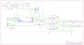
hii, i am trying to build a 750w 48v bldc motor controller, the problem i am facing right now is, my controller is not self starting the motor. it always need little push to rotate the motor, after little push motor respond correctly to throttle until i did not bring throttle to zero position. it seems like there is problem with high side mosfet not turning on at the start, so tried changing bootstrap capacitor from 1uf to 10uf to 22uf but still no success. please help me with this problem i am really stuck in this. please find attach schematic of controller.
 

Attachments

Thread Starter

Swap_4342

Joined Jun 3, 2018
16
i am using hall sensors for commutation of motor,hall sensors are connected to 4, 5, 6 pin of mc33035 logic control around mc33035 is working fine, i have tested. problem is in mosfet driver circuit.
 

MisterBill2

Joined Jan 23, 2018
18,167
I look at the wiring diagram and I do not see the motor windings shown. So either I am missing something or else there is a lot missing.
How much current is the motor driver drawing when the motor is actually spinning? It is quite likely that the motor will not start with such a low voltage, and so that may be a large part of your problem.

AND, once again, I do not see any motor connections on the drawing provided. Nor do I see any hall sensors, although I can guess where they connect,

s this an actual system? Or did you acquire a 750 watt 48 volt motor and start creating a circuit to drive it?
 

MaxHeadRoom

Joined Jul 18, 2013
28,617
I look at the wiring diagram and I do not see the motor windings shown. So either I am missing something or else there is a lot missing.
How much current is the motor driver drawing when the motor is actually spinning? It is quite likely that the motor will not start with such a low voltage, and so that may be a large part of your problem.
AND, once again, I do not see any motor connections on the drawing provided. Nor do I see any hall sensors, although I can guess where they connect,
s this an actual system? Or did you acquire a 750 watt 48 volt motor and start creating a circuit to drive it?
You need to look up Motorola AN1046 it shows the application of a 24v BLDC motor drive using the MC33035.
When this IC was launched, Motorola were offering a development PCT board for the AN1046 shown on P9 of which I obtained one at that time, Not sure if they are still available, probably not.
The board included the MC33035, MC33039 and MPM3003.
Max.
 

MisterBill2

Joined Jan 23, 2018
18,167
You need to look up Motorola AN1046 it shows the application of a 24v BLDC motor drive using the MC33035.
When this IC was launched, Motorola were offering a development PCT board for the AN1046 shown on P9 of which I obtained one at that time, Not sure if they are still available, probably not.
The board included the MC33035, MC33039 and MPM3003.
Max.
OK, but if the driver is set up for a 24 volt motor and the supply is 24 volts there may be less than adequate torque to spin up a 48 volt motor. BLDCs are not like brushed motors.
 

Thread Starter

Swap_4342

Joined Jun 3, 2018
16
I look at the wiring diagram and I do not see the motor windings shown. So either I am missing something or else there is a lot missing.
How much current is the motor driver drawing when the motor is actually spinning? It is quite likely that the motor will not start with such a low voltage, and so that may be a large part of your problem.

AND, once again, I do not see any motor connections on the drawing provided. Nor do I see any hall sensors, although I can guess where they connect,

s this an actual system? Or did you acquire a 750 watt 48 volt motor and start creating a circuit to drive it?
Sorry for the schematic, it is not showing every detail, i built it for my reference, I don't think low voltage is the problem, if i connect the logic area (circuit around mc33035 without mosfet driver) directly to mosfet motor start by itself and works fine, but mosfet get hot after sometime, that might be because current and voltage from logic area is not sufficient to turn mosfet fully on.

Total current draw by controller is around 1-2 amps at no load, at 2430rpm
 

Thread Starter

Swap_4342

Joined Jun 3, 2018
16
Sorry for the schematic, it is not showing every detail, i built it for my reference, I don't think low voltage is the problem, if i connect the logic area (circuit around mc33035 without mosfet driver) directly to mosfet motor start by itself and works fine, but mosfet get hot after sometime, that might be because current and voltage from logic area is not sufficient to turn mosfet fully on.

Total current draw by controller is around 1-2 amps at no load, at 2430rpm
motor phase wires are connected in between 3 h bridge of mosfets,

i think the problem, mc33035 give spwm signal on low side gate driver pin, so at the start at zero throttle position there is zero volt at every mosfet gate pin, according datasheet of ir2101, bootstrap capacitor needs low side mosfet turn on charge, when i increase throttle on of the low side mosfet turn on, but not the high side mosfet from commutation sequence at start because bootstrap capacitor wasn't charge. since one of the low mosfet is on, bootstrap capacitor respect to that bridge gets charge. when i give littele spin to motor mc33035 activates next two high and low side mosfet accourding signal. since on of the bootstrap capacitor is charged in previous step, it drives high side mosfet in that step, and thats how motor starts running.
i am not 100% sure on this i am just guessing.
sorry i cant show the waveforms of the circuit i dont have an oscilloscope.

also one thing i noticed is that if i stop motor at low rpm by hand i do feel the torque for 1-2 seconds after that torque disappear, so my conclusion is charge at mosfet gate pin discharges after 1-2 second at standstill by itself.

again i am just a noob in electronics so please do correct me if i am wrong.
 

Alec_t

Joined Sep 17, 2013
14,280
How did you measure that if you don't have a scope? Does your meter have a peak-reading function? A typical simple meter will only register a sort of average value when the voltage is pulsing (e.g. if there are high frequency parasitic oscillations).
 
Top