BLDC 3 phase / question about hall sensor position / adjustment.

Thread Starter

aspiespot

Joined Dec 14, 2018
21
Hello,

I am trying my very best to understand the way hall sensors work on BLDC motors , After reading and watching videos I now understand in basic terms the function of the hall sensors.

It would be a great help if anyone could answer the following question for me.

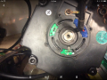
*the picture shows a BLDC 3 phase motor, the hall sensors are fitted in a holder which can be rotated , when fitted a new pcb to motor or new motor to pcb would you need to rotate / adjust the holder as I would think this would change the timing for the windings ? (I suppose a bit like adjusting the timing on an older car) is this correct ? or is there a set up procedure ?

thanks for your help, Darren.
 

Attachments

MaxHeadRoom

Joined Jul 18, 2013
28,686
I have installed a few encoders that have the hall tracks on them and it is necessary or at least easier to use a double beam scope to align the halls with the three phases.
See the attached pdf.
I use three 1k resistors attached to each phase and connect the other three ends together to create a virtual zero point.
this is the ground for one of the scope channels for one of the phases.
The other scope lead goes to the respective hall or track output.
You also need to back feed the motor ~ 200rpm or so using a drill or other means, to generate the three sine waves..
Max.
 

Attachments

Last edited:

Thread Starter

aspiespot

Joined Dec 14, 2018
21
I have installed a few encoders that have the hall tracks on them and it is necessary or at least easier to use a double beam scope to align the halls with the three phases.
See the attached pdf.
I use three 1k resistors attached to each phase and connect the other three ends together to create a virtual zero point.
this is the ground for one of the scope channels for one of the phases.
The other scope lead goes to the respective hall or track output.
You also need to back feed the motor ~ 200rpm or so using a drill or other means, to generate the three sine waves..
Max.
Hi Max,

thanks that's a great help,

That may explain some previous issues I have seen when replacing a new PCB , as the motor had unusual noises and the PCB was replaced and the motor still has unusual noises. The supplier advised that we needed to replace the PCB and Motor as a matched pair.
Looking back I would think the hall track just needed setting up ?

For a number of years I worked in a workshop mainly fixing mechanical issues , the electrical engineer chap in the workshop would set up these motors by ear with no equipment ?

Thanks you've been a great help,

Regards Darren.
 

shortbus

Joined Sep 30, 2009
10,045
For a number of years I worked in a workshop mainly fixing mechanical issues , the electrical engineer chap in the workshop would set up these motors by ear with no equipment ?
Mechanics back in the day did the same thing with engine timing, but for the best performance at all speeds it needs to be done correctly.
 
Top