BJT Switching circuit

Thread Starter

vlagvlag

Joined Nov 5, 2016
9
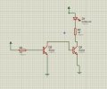
Hi guys im kinda new to electronics and i've been experimenting with some 2n2222 npn transistors, i've built this circuit and tried to measure measure currents and voltage drops across each component, what i think should happen is that if the base of Q1 is connected to the +5V supply , this should give( (5-0.7)/470) 9 to 10 mA i think is enough to get Q1 to saturation , now if i understand this correctly Q2's base should be connected to ground if Q1 is on , and so Q2 is off , then the LED shouldn't be lit , but it's actually on all the time so is there something i'm missing here? , also when i tried to disconnect the wire connecting the base of Q2 from the collector of Q1 and i would touch the end with my finger i noticed the LED is emitting again can someone explain this? , also i've over 10 of this transistor and i've tried replacing both of them with the same result , any help would be appreciated .
 

Attachments

simozz

Joined Jul 23, 2017
170
Hello,

My suggestion is to try to build the real circuit.
Simulators can lead to confusion if you are beginning to electronics.

Regards,
simozz
 

crutschow

Joined Mar 14, 2008
38,503
Your posted circuit cannot work as shown.
You need a resistor from Q1's collector to V+ to provide a turn-on current for Q2's base.

If the LED is on with that circuit, then theirs an error in your wiring.

R1 can be a lot smaller also.
Q1's base current needs to be only about 1/10 of it's collector current for good turn-on saturation.
 

Jony130

Joined Feb 17, 2009
5,598
Add 1kΩ resistor between Vsupply and Q1 collector. And the circuit will start working as you expected.
Without the resistor at Q1 collector, Q1 simply cannot pull his collector voltage low. Now withoud this resistor Q1 behaves as a two back-to-back PN diodes.
And this is why Q2 is always ON.


mtonge

Joined Apr 19, 2016
93
I think I understand your thinking. Try connecting the collector of Q1 to vcc with a resistor (10k ?). The base of Q2 is still connected to the collector of Q1. Now when Q1 is turned on (voltage applied to base) Q2 will turn off, because the base of Q2 will see little or no voltage drop accross Q1. When Q1 is turned off (no voltage to base) Q2 will turn on, because the base of Q2 will see the voltage drop across the resistor. I think I'm right, but I could be wrong. I'll breadboard it when I get home.
 

Thread Starter

vlagvlag

Joined Nov 5, 2016
9
ok, i think now i understand what i've done wrong here and after reconnecting it as you guys suggested it worked, but that still doesn't explain why when i disconnected Q1 entirely the LED would light up when i touch the base of Q2 i don't understand why would this happen?, also in this inverter circuit does Q1 behave as two diodes also? , if so what is the purpose of doing this instead of connecting Q2 directly without the need for Q1?
 

Attachments

AnalogKid

Joined Aug 1, 2013
12,126
Post #6 looks like the internal schematic of a 7404.

With the Q2 base floating, touching it injects enough electrons to turn it on slightly. It takes only microamps of base current to see some effect.

ak
 

crutschow

Joined Mar 14, 2008
38,503
but why not supply Q2 directly ?
Because the extra Q1 transistor means the circuit driving the input doesn't have to supply current to turn on Q2.
All it has to do is stop sinking current from the emitter of Q1 and allow Q1 to shut-off, which diverts it's base current to the base of Q2.
It makes a faster circuit with less drive current required by the source.

Another advantage is that Q1 can be easily built with multiple emitters to give a multiple input NAND gate.
 
Top