 Facebook
 Google
 GitHub
 Linkedin
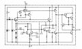
thought could get inspiration from national semiconductor book. few hours later, thought understood (every noob thinks so before testing...)
what was this noob expecting? (it's not really same as schematic from book : it uses voltage regulator it says but havent learnt that yet and also added vbe multiplier)
Thanks to Q6, emitter of Q5 should be about 3Vbe and as Vbe multiplier, collector of Q5 about 5V so emitter of Q2 about 1v
The output(collector of Q2 will be inverted to input right? ) expecting about 6v there thanks to Vbe multiplier with Q2 but not working
Q11 and Q10 is the problem?
Please assist TS and kindly ask any question : Think I understand circuit but maybe not (if did, will work )
Thanks
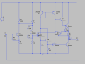
Attachments
-
 367.2 KB Views: 26
 -
 411.8 KB Views: 22
 -
3.7 KB Views: 7


