BJT-H bridge driving question.

Thread Starter

jpborunda

Joined Apr 9, 2014
55
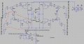
Hello guys, I'm designing a H-bridge with bjts, and I have a question regarding the "low side'' part. The high side are pnp transistors, so I'm going to drive them with a npn as the schematic shows. However, I'm not sure how to drive the low side part. Can I simply use another npn and resistors to drive it, as I have it right now? (See schematic please) The simulation gives the desired output at R13, but I need some validation.

The actual components I'm going to use will have to be rated for 200V, my local store has some 2SA1553 and 2SC4029 darlingtons which are said to be "complementary", they are rated for 230 V.

V3, V4, V8, V7 are digital outputs from an Arduino Microcontroller to control the bridge.

EDIT: Can I use 1n4007 diodes for the bridge protection? Again, my local store doesn't have exactly a lot of choices...

If there is another thing I'm missing please do tell.
 

Attachments

MikeML

Joined Oct 2, 2009
5,444
If the load is only 500 Ohms, then the Q4, Q5 pre-drivers are not necessary. Assume that if this is driven from a uController Port pin, it can source about 20mA @4V (more than enough to saturate the NPN Darlington). Do you even need a Darlington? What is the Vce breakdown voltage of U4 and U5?

Your PNP side is badly screwed up (that's a technical term). Have you done a power dissipation calculation for R1 and R5, to say nothing of the Vce Breakdown of Q2 and Q3?
 

Thread Starter

jpborunda

Joined Apr 9, 2014
55
The load will be 1kOhm max, and yes the microcontroller sources 5v@20mA (max). The Vce for U4 and U5 is 230 V. The signal will be on for small periods of time (100Hz, 500µs of ON time), so I'm calculating a power disipation for R1 and R5 to be 1.9W.

I've made a mistake with Q2 and Q3, Im going to be using the 2N3439, which has a Vce breakdown of 450V for Q2 and Q3. Can you elaborate on how the pnp side is screwed up please?
 

MikeML

Joined Oct 2, 2009
5,444
I'm more worried about the minimum resistance of the load...

All four arms of this H-bridge require switching devices that have a breakdown voltage greater than 300V; more if the load is inductive...

At the speed you are switching this, the 10K resistors R3, R4, R 10, and R12 are way too high to turn off the the attached switching transistor. Have you simulated this?
 
Last edited:

DickCappels

Joined Aug 21, 2008
10,661
The 1N4007 should be fine if the current spikes are well below 10 amps and the rise time of the spikes are quite a bit longer than the 1 microsecond maximum forward recovery time.

Advice you for which you did not ask:

Beware to overlap during switching; you might want to intentionally add some dead time between turning one pair off and turning the other pair on.

The 0.1 uf capacitor can cause a large current spike each time the bridge switches. If the spike is too high, it can cause eventual failure of the capacitor and the switching transistors, so you might want to have a close look at the current waveform in your simulation and check it against the specifications for your output transistors and the capacitor itself. If necessary add some current limiting or resistance to limit the spike.
 
Top