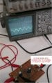
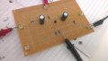
I just measured it again, on the working machine. Theres a picture of how I measured the voltage drop across the 10K resistor just to make sure I'm doing it right.
According to those readings (rounding up/ down) (0.5/1k) / (0.3/10K) = 16.667? - If that is correct. I'm HAPPY with that! haha
I just measured it again, on the working machine. Theres a picture of how I measured the voltage drop across the 10K resistor just to make sure I'm doing it right.
mmmm... not sure about that. In your picture you're measuring the two leads of the Rresistor with respect to ground. So the voltage drop will be the difference between these two measures. Is this difference equal to 0.3V you're talking about?
Are you doing that?
Wouldn't it be easier to just measure with only one oscilloscope probe between the two leads of Rresistor? - don't connect the other probe when you do this. Are you having the same results as before?
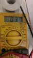
If you measure with the multimeter, you must put it in AC voltage and not DC!!! because you're measuring ac signal on Rresistor. In your picture it seems you put it in DC !!!
Also you say you got 740mV but in your picture I see 3.7 ??? - too much confusion here .
Also, with a multimeter, the value you see is the rms of the ac signal (root mean square) and not the Vpp. This is not a major problem only and only if you use the multimeter also for measuring Vout.
If you use the multimeter capture for V(Rresistor) and the oscilloscope for the Vout (over RL) your conclusions will not be right because you're not comparing same things (rms with Vpp).
I'm convinced you're very closed to demonstrate the good functioning of your amplifier. But knowing what to measure and how is as important as a good design.
Please, do as follows:
* Only use the oscilloscope
* With only one probe, measure the voltage drop in Rresistor and note the result in a paper.
* With only one probe, measure the voltage drop in RL and note the result in a paper.
* Deduce Iout (Vout/RL) and tell us
* Deduce Iin (Vresistor/Rresistor) and tell us
* Deduce Iout / Iin and tell us
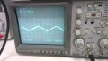
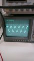
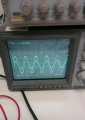
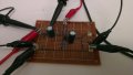
I figured if the tab was pointing to '200m' it was 200 * 3.7...anyway. I went and saw my lecturer, was told the 10K resistor was too big it had to be a small value (50 Ohms) to get the 1 to 1 voltage - I went back and soldered the 50 Ohm Resistor back in and as you said measured 1 channel at a time. I have provided pics of input and output voltages. I then measured with the osciliscope across the 50 Ohm resistor like you said. Picture provided just to make sure I did it correctly as well as the result.
Input is 500mV
Output is 480mV
Voltage across 50Ω resistor ~ 100mV
Yeah, and you still did a mistake while reading Vresistor.
I see 10mV on it and not 100mV !! - look again at your oscilloscope screen. You have a Vpp = 20mV (not 200mV), so amplitude is 10mV and not 100mV.
However, this makes a voltage drop in Rresistor TOO high with respect to LTspice simulation, which gives about 1mV amplitude. Are you using 50Ω or 500Ω?
Another issue; Is voltage across RL 750mV or 480mV?
I'm using 50 Ohms. That's what confuses me...when I use 2 probes on either end I get 500input and 480output...but when I use 1 probe I get 750 :S as for the 100mV there's 5 divisions...I just multiplied 5 by 20. That means all my other readings are wrong.. How are you reading it? I don't think I'm interpreting it correctly.
Each probe has a positive and reference leads. But internally to the oscilloscope the reference lead of channel 1 is connected to the one of channel two. So if you use two probes at the same time, be sure you only have ONE SINGLE reference point. In practice, you can only connect one of the two reference leads because both are internally connected.
If you measure with two different references, you're making a shortcut between them and your circuit will not behave as it should.
If your input voltage is 0.5Vamplitude and voltage on 50 Ohm Rresistor is 10mV, this means an input current of 0.2mA instead of 0.02mA as it should (remember that we made the design so as to have Zi = 20K).
This means that the input impedance seen by the source is about 2K and not 20K as per design. In this case there is a 10 factor somewhere. I hope you follow me.
At this stage, and assuming that all resistors have the correct value (did you check with your multimeter or by looking at their color identification? >> do it with the multimeter now and without Vcc) disconnect the input source and check again the DC operation point.
Connect your circuit to Vcc and give us the DC voltages for:
* Vcc (well, I suppose this is fixed to 20)
* VB
* VE
I just went online and double checked using a resistor calculator to double check. They are all correct values for the resistors and both caps are 470uF as for VB and VE, I'll have to do that tomorrow since the lab has been closed for the night.
Also, and just to be sure, in your second picture, when you measure Voltage on the 50 Ohm resistor, there is a probe lead on the right side connected to ground. Is this connected to the other channel of the oscilloscope? or not? SHOULD NOT.
Please confirm. Otherwise, remove it when you measure the voltage across the 50 Ohm resistor.
VB - VE must be ~0.7V, otherwise the transistor is not well biassed or there is a problem with that transistor. The transistor will not work in the linear region.

 Facebook
 Google
 GitHub
 Linkedin



 .
.