 Facebook
 Google
 GitHub
 Linkedin
Hi
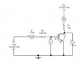
to find the input characteristic of bjt Transistor We must change the the voltage VBB and meausre the current IB
but the voltage VCE must be const how we can keep the voltage const. ?
in the simple bias circuit the VCE=VCC-Ic RC IC=β ΙΒ when the VBB change the current IB change
the VCE NOT KEEP constant
tnak you
George
Attachments
-
 50.3 KB Views: 19


