 Facebook
 Google
 GitHub
 Linkedin
Hi everyone!
My name is Eleni and I am a freshman in the department of automation engineering at TEI of Thessaloniki,Greece.This semester we have in our programm analog electronics which I love but I can't quite understant sometimes.
I have a specific circuit we have to solve and I am not sure how to continue...
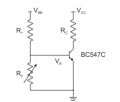
These are all the specifications given:
VBB=VCC=5V
R1=4.7k ohm
RC=220 ohm
I found that R2 should be 0.7873k ohm so that the voltage at the base of the transistor is 0.7 V.
1st)Using that I found the current (-11.31 mA) and the voltage (-2.513 V) at the collector.
2nd)After that at a IC-VCE I have to put the Q and design the load line.
Can someone tell me if what I did is wrong and explain to me how to do the second part of my "homework"?
I know almost nothing about transistors and our professor nver explains to us what to do,so I would appreciate any help given.
Thank you so much!!!
My name is Eleni and I am a freshman in the department of automation engineering at TEI of Thessaloniki,Greece.This semester we have in our programm analog electronics which I love but I can't quite understant sometimes.
I have a specific circuit we have to solve and I am not sure how to continue...
These are all the specifications given:
VBB=VCC=5V
R1=4.7k ohm
RC=220 ohm
I found that R2 should be 0.7873k ohm so that the voltage at the base of the transistor is 0.7 V.
1st)Using that I found the current (-11.31 mA) and the voltage (-2.513 V) at the collector.
2nd)After that at a IC-VCE I have to put the Q and design the load line.
Can someone tell me if what I did is wrong and explain to me how to do the second part of my "homework"?
I know almost nothing about transistors and our professor nver explains to us what to do,so I would appreciate any help given.
Thank you so much!!!
Attachments
-
 9.9 KB Views: 8
 -
 4.1 KB Views: 9
 -
 223.1 KB Views: 7
.png")


