Bipolar stepper motor driver problem

Thread Starter

CVMichael

Joined Aug 3, 2007
419
I made a bipolar stepper motor driver with L298 and L297, it looks simmilar to this:

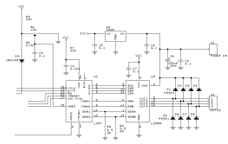
I tried it with a few motors and it worked fine.
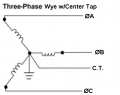
Recently I bought a new motor: KP35FM2-035 1.8 DEG/STEP
It looks like this:

I used it on my motor driver and it behaves really strange.

Here's what is does:
1) No matter how much voltage I apply to the "power in" it is still weak, I can turn the motor shaft by hand very easily...
2) It does not move in one direction only, it turns erratically, I mean, the direction input to pin 17 of L297 is always constant, it should move only one direction, but it moves a few steps in one direction, then another direction, and so on... and if I "help it" (moving it with my hand), it moves in the direction I help it to move...
3) Even if the enable pin 10 of L297 is OFF it is still turning erratically, but it should not move at all !
4) Same as enable, if I reset pin 20 of L297 is ON, it is still turning erratically... it should not turn when it is reset !!

BUT... if I change to any other motor, it works fine, even if I don't turn the device off, and I swap the motors while the device is ON.

I have 4 of these motors, none of them work...

By the way.... all other motors (that work) the resistance on the coils have 12 ohms and less, but this motor has ~ 37 ohms.

Because of that I tried to change the resistors R8 & R9 to 1 ohm, 1.5 ohms, 10 ohms, 47 ohms, none of them work.... and I brought the voltage all the way to 26 volts, and I burned the L298 chip, but I have no idea how because the specs show it should take up to 50 volts :confused: thank god I bought extra ones...

Anyways...

Anyone knows how to get it to work ?
 
Last edited:

Thread Starter

CVMichael

Joined Aug 3, 2007
419
How many wires does a 3-phase motor have ?

The one I have it has 4 wires, and measuring the ohms on the wires, I get 2 wires with ~37 ohms, and another 2 wires with ~37 ohms...
 
Last edited:

SgtWookie

Joined Jul 17, 2007
22,230
It could be three phases in a wye configuration with a center tap. See the attached.

You need to measure the resistance between all four wires in a number of combinations.
WHT - YEL
WHT - RED
WHT - BLU
YEL - RED
YEL - BLU
RED - BLU
If it's bipolar, you'll get 37 Ohms between two pairs of wires, say WHT-YEL and RED-BLU - but open from WHT to RED or BLU, and YEL to RED or BLU. If it's wye with a center tap, you'll get something like 37 ohms between yel-red, red-blu, blu-yel, and about half that from white to any of the other three - assuming white is the center tap, but I don't know at the moment, and I can't find a datasheet for your motor.
 

Attachments

Last edited:

Thread Starter

CVMichael

Joined Aug 3, 2007
419
I sent a request, i'm waiting for a reply from them...

I am at work right now, and I cannot see exactly on what wires I get resistance...

But I'm pretty sure that I got 37 ohms on 2 wires (and only those 2), and then 37 ohms on the other 2 wires.... therefore I'm pretty sure that it is a bipolar stepper motor... but I will check again when I get home to make sure.
 

Thread Starter

CVMichael

Joined Aug 3, 2007
419
I did not get a reply fro them yet... but I measured the resistance on the wires of the motor:

Blue & Red = 37 ohms
White & Yellow = 37 ohms

That's it... I tried all other combinations, and nothing...
 

SgtWookie

Joined Jul 17, 2007
22,230
Hmm, OK. I'll make a guess that your steppers should run on about 12v to 13v.

Wait, the Jameco site says 24v, 500mA - but 24v/37 Ohms = 648.7mA. (I'd tried to get on Jameco's site multiple times earlier today, and couldn't get in; their server was down.)

But since you're running a chopper driver, you should be able to go about double that if your Vref is properly chosen. If your Rsense are indeed 0.5 Ohms, your motors are rated for 500mA, so E= IR = 0.25 = what your Vref should be set to. Make sure that your Rsense are non-inductive resistors (not wirewound) and that they have a good ground.

You'll have to be careful to not exceed the 7805's max input of 35 volts - and it'll get mighty warm if you're that high.

Your C4 is 1nF? The example in the datasheet I have shows 3.3nF; you might want to bump yours up a bit. If the oscillator is running too fast, the driver will spend a lot more time in the linear region generating heat. :eek:
 
Last edited:

Thread Starter

CVMichael

Joined Aug 3, 2007
419
Just to update you.

Actually changing the Vref made the whole diference... before i did not have a variable resistor there... actually when I designed the board, I used the schematic from somewhere else, and there it did not have a variable resistor, and when I test it first time, I tested it with another motor and it worked then.

Anyways... now I changed it to a variable resistor and it works now...

But... it seems to work the same if I pass a certain threashold... and it works fine if the vref is the same as "power in", therefore, I don't understand why we need a variable resistor at all... can't I just connect the Vref to the power in, and that's it ?

Also, how can I increase the power (strength) of the motor ? It seems like it has the same strength regardless of how much power I put into the device... I mean, I tried with 6V and all the way to 20V and it seems to have the same strength

The pin 16 OSC, I connect it directly to a microcontroller (PIC16F877), same with all others like direction, cw/ccw, enable, reset, half/full.
 

SgtWookie

Joined Jul 17, 2007
22,230
Actually changing the Vref made the whole diference... before i did not have a variable resistor there... actually when I designed the board, I used the schematic from somewhere else, and there it did not have a variable resistor, and when I test it first time, I tested it with another motor and it worked then.

Anyways... now I changed it to a variable resistor and it works now...
OK, so whichever motor you're using, set Vref to measure the same voltage as you would get by passing the motor's current rating through your sense resistors. In the case of the motors you were having problems with, that's E=IR, or Vref = MotorCurrent * 0.5 Ohms, or Vref = 0.5A X .5 Ohms = 0.25V. Whatever other motor you wish to use, just plug it's current rating into the formula, set your Vref, the input voltage to 2x the motor's voltage rating (or 35v, whichever is lower) and you'll be feeding your stepper motor properly.

But... it seems to work the same if I pass a certain threashold... and it works fine if the vref is the same as "power in", therefore, I don't understand why we need a variable resistor at all... can't I just connect the Vref to the power in, and that's it ?
No! Vref has a range of from 0v to 3v. Don't set Vref outside of that range as you will apply full input voltage with no current limit to the stepper motor. I hope that you have a 100nF cap from the Vref input to ground, also - otherwise, your Vref will not be stable.

Using the chopper drive, you can supply the motor with up to twice it's rated voltage, within the limits of your other devices in the circuit. I already mentioned that the 7805 is limiting you to 35v right now. Were that powered from somewhere else, you could go up to the maximum limit of the L298, which is 46V - but I suggest you stay a few volts below that. It's not good to run a component at it's maximum limits, particularly if you want it to last.
Also, how can I increase the power (strength) of the motor ? It seems like it has the same strength regardless of how much power I put into the device... I mean, I tried with 6V and all the way to 20V and it seems to have the same strength
What did you use to measure it's strength with? Simply gripping the shaft with your fingers won't be very accurate. Try making a lightweight lever about 6" long with a hopper attached into which you can place fishing weights. You'll find that the higher the voltage goes with Vref set at 0.25v, the more weights it can lift.

The pin 16 OSC, I connect it directly to a microcontroller (PIC16F877), same with all others like direction, cw/ccw, enable, reset, half/full.
No, that's not correct! The OSC pin 16 must have a 3.3nF capacitor to ground, and a 22k resistor to Vcc (5V). Otherwise, the chopper drive will not function properly, and you risk damaging the L297, L298 and your stepper motor. There is no reason to connect the OSC to your PIC, as it will unnecessarily use an I/O pin, and require you to use a timer and an interrupt to continually toggle the state of the pin.

A 3.3nF cap with a 22k resistor will cause the chopper to oscillate at a 20kHz rate, which should be optimal. If you can hear it oscillating and find it annoying (a very high-pitched whine) you could decrease the capacitor to 2.2nF, which would give you about 30kHz operation - or keep the capacitor the same and reduce the resistor somewhat. The oscillator frequency = 1/0.69 RC. You really don't want to go over 30kHz, or your driver (L298) will start spending too much time in the linear region, generating heat.

Vref, Rs1, Rs2, and OSC are critical to the proper operation of the L297/L298 pair. If they are not set properly, there is no hope of getting the driver to function properly.

Also, you must use the bypass capacitors as shown.
 
Last edited:

Thread Starter

CVMichael

Joined Aug 3, 2007
419
Hi,

Thanks for checking in...

Yesterday I was busy with other things, so I did not have time to make the changes... hopefully I will have time today.

I just want to add that in my last post I made a mistake when I said that "The pin 16 OSC, I connect it directly to a microcontroller"
Actually, The pin 18 CLK is connected to microcontroller... I don't know why I confused them before. When you said about C4, I started thinking about the clock, not the osscilator, and then I just mixed everything up...

Now I have another problem, that worked fine until now (2 days ago): I get an error when I try to write the updated program to the microcontroller. But I will make a new thread about that when I get home and if I can't solve the problem.
 

Thread Starter

CVMichael

Joined Aug 3, 2007
419
Yesterday it was a somewhat productive day...

I fixed the problem with the programming the microcontroller, so I was able to update the program on it...

I also made the changes you told me.
I added a variable resistor 10K on +5V and ground, and middle pin on Vref with a 100nF capacitor on ground and Vref.

The osc capacitor was already 3.3nF...

I also ordered BYV27-100 diodes to replace the 1N4007's I am using right now... I will get them in the next few days
Do you think the diodes make a diference in performance ? are the new diodes that are ordered better ?

But I still did not get any extra performance from the change, the motor is still weak

PS. I ran the device at ~14 Volts, I did not have time to try other values...
 
Last edited:

SgtWookie

Joined Jul 17, 2007
22,230
I fixed the problem with the programming the microcontroller, so I was able to update the program on it...
:)

I also made the changes you told me.
I added a variable resistor 10K on +5V and ground, and middle pin on Vref with a 100nF capacitor on ground and Vref.
OK. Is the driver circuit on a breadboard, or have you assembled it on a perfboard? I'm wondering about the reliability (and resistance) of your connections.

Did you verify the resistance of Rs1 and Rs2? On your schematic, they're R8 and R9, 0.5 Ohm 2W resistors. If you pass exactly 1 Amp through either of them, you should read exactly 0.5 Volts across it. It's more accurate to test small values of resistance that way instead of using an ohmmeter. It's more important that they are EQUAL rather than exactly 0.5 Ohms. If they aren't quite 0.5 Ohms, you can make corresponding adjustments to the formula for adjusting Vref.

But, you can more or less verify that by checking the voltage across the stepper's windings when it's powered by the bridge, but stationary (motor not turning). You'll need to filter the high-side source using a fairly large resistor and a small cap, like 1M to 100k and 10nF to 100nF. This will integrate the chopping from the bridge into something more resembling a DC level. When you're powering the motor using 30v, you should actually read somewhere around 20v across the motor if the bridge is working properly.
E=IR
R= 40 (this is a wild guess at what the impedance of your coils will be at 20kHz; more importantly it's what the manufacturer specifies the resistance to be.)
I = 0.5A (the current you've programmed the bridge to provide by setting Vref to 0.25v)

Then step the motor, and check the voltage across the other winding. They should be about equal.

If you change your Vref slightly, you should notice that the voltage across the windings increases and decreases.

The osc capacitor was already 3.3nF...
That should be fine. You have a 22k resistor from pin 16 to Vcc, right?

I also ordered BYV27-100 diodes to replace the 1N4007's I am using right now... I will get them in the next few days
Do you think the diodes make a diference in performance ? are the new diodes that are ordered better ?
Yes, they're certainly better than the 1N4007's. Hard to say if you'll notice an improvement though.

But I still did not get any extra performance from the change, the motor is still weak

I ran the device at ~14 Volts, I did not have time to try other values...
Well, the motor is rated for 24v. You're running at half the rated voltage. Don't forget that the bridge in the L298 is made from BJT's (transistors) and each side of the bridge will have a drop of nearly a volt across it when saturated - plus the 0.25v drop across Rsense. So if you're powering the bridge with 14v, the most your stepper can see is around 12v.

If you want to get maximum performance from the motors, you're going to have to get the bridge supply up around 45v - but in order to do that, you'll have to power the 7805 with something else, or you'll fry it.

The whole point of using a chopper driver is to get the maximum power and stepping rate out of your stepper. By using double voltage drive, the current flow through the motor windings gets established far more quickly, and the chopper drive keeps the maximum current limited to a safe value.
 

Pich

Joined Mar 11, 2008
119
Your problem with eratic operation could be cause by the resonance of the motor at 37 ohms coil resistance (very high for a stepper motor) it is highly inductive. try switching to half steps on the L297. I think the motor is rated at .25 amps set your current resistor and pot to match. Make shure that the stepping pulse rise time from the processor matches the L297. At low speed with proper stepping the motor will produce maximum torque and that's all you can get without overheating it. If you wish to get higher speed you need to boost the voltage to the max the L298 will allow, rule of thomb is 4 to 20 times the rated motor voltage, with that high of coil resistance your max speed may be limited.
you should usse high speed diodes they will keep the L298 cooler
 

SgtWookie

Joined Jul 17, 2007
22,230
Your problem with eratic operation could be cause by the resonance of the motor at 37 ohms coil resistance (very high for a stepper motor) it is highly inductive.
Hi Pich,
Do you have the datasheet for his stepper? The only specs I could find for it were on Jameco's website; 24v, 500mA, 40 Ohms. That's why I had him set his Vref to 0.25v; he's using 0.5 Ohm resistors for Rs1 & Rs2. Have no info as far as max step rates, etc.

try switching to half steps on the L297.
That's an idea.
I think the motor is rated at .25 amps set your current resistor and pot to match.
Nope, .5A, and that's already been addressed.

Make shure that the stepping pulse rise time from the processor matches the L297.
Care to elaborate on this? I'm not quite following you.
At low speed with proper stepping the motor will produce maximum torque and that's all you can get without overheating it. If you wish to get higher speed you need to boost the voltage to the max the L298 will allow, rule of thomb is 4 to 20 times the rated motor voltage, with that high of coil resistance your max speed may be limited.
Ahh, I wouldn't try to run a stepper at anywhere near 20x the rated voltage. :eek:
At any rate, the L298 is limited to 46v absolute maximum, but due to the design he used, 35v is as high as he can go without destroying a 5v regulator he's using to power the L297 with. As I mentioned above, his motor is rated for 24v; at 45v input to the L298 he won't even be able to double the rated voltage, and the L298 and Rsenses will steal 2v right off the top. 1.8x is the best he can get.

you should usse high speed diodes they will keep the L298 cooler
He has them on order. Not sure what kind of a performance increase he'll get.

It might be helpful for him to lower the L297 chopper oscillator frequency somewhat. Bringing it down from 20kHz will make the chopping audible, but would help reduce the effects of inductance.
 
Last edited:

Pich

Joined Mar 11, 2008
119
I'm afraid I don't have a datasheet for the motor Wookie, yuo found more than me. I just read an artical on it. This motor is rated at 24 volts I can see can't overdrive it by much
 

Thread Starter

CVMichael

Joined Aug 3, 2007
419
Hi Guys... thank you so much for helping me.

Since SgtWookie told me to change the Vref input, the motor is not acting erratic anymore, so I fixed that problem a while ago...

The next problem was that it was not strong, but:
I got the diodes, and changed them... big difference... now the motor is stronger, and I think it's running to it's max because it starts to get worm and hot if it's running for a long time... nothing else gets hot tough.

By the way, i'm running it with rechargable AA batteries, at 2200 mA each, I have 14 of them in series, so it runs at 1.2V * 14 = 16.8 Volts

So the input for the LM7805 I don't have to put at the total voltage, I can put it after 6 AA or 8 AA of the 14 AA batteries...

So... for now everything is fine... the motor is still not as strong as I wanted to, but now I realized that i'm using a small motor for the traction that it needs to do, so I think I should change the motor to a bigger one.

Now i'm working to program the microchip to balance the robot. Yes, I am working to make a balancing robot.

Anyways... thank you for helping me. I think I'll start new thread if I can't figure out the programming for balancing the robot.
 

SgtWookie

Joined Jul 17, 2007
22,230
Well, it seems like you've made good progress. Glad to hear the new diodes helped out!

But it seems to me that your motors require a heck of a load with all of those batteries in series, and the basic motor itself is probably rather heavy.

Consider getting some of these motors:
http://www.jameco.com/webapp/wcs/st...toreId=10001&catalogId=10001&productId=171601

They're low voltage pancake-type unipolar steppers, and the price is pretty decent if you get at least 10 of them. They're rated for 7V in unipolar mode, but if you run them bipolar, that's 14v, and with a L298, you could use a 28v supply (23 batteries in series) for maximum step rate.

If you wanted to keep things simple, you could just run them unipolar from a 7v supply, and use something like a ULN2803A Darlington driver to control the current through the windings. You won't get as high speed or torque as the double-voltage drive.

Another option could be to use a MC3479, SLA7020, UCN5804, L293D or the like stepper driver IC's.

Keeping your 'bot lightweight will help maximize the time you'll get out of your batteries. Starting off with heavy steppers that require lots of juice means you'll have to build the skeleton sturdier, lug lots more batteries around, etc etc - it's a nasty spiral.
 
Top