Facebook
 Google
 GitHub
 Linkedin
Hi.
I bought Bionaire BW2300-N window fan, which does what it's supposed to, and on LOW setting it's quiet enough to allow me to sleep. However, current fan's controller is quite bad, as it reads temperature all the time, there is no temperature threshold, no delays, and when fan starts, it starts on HIGH and then it goes to option that I set it to.
So for example, fan is set to 60F (minimum) intake on low speed, it turns on in HIGH mode, second later is goes into LOW mode, temperature sensor drops to below 60F and fan shuts down, about 3 seconds later temperature raises above 60F and fan turns ON again. That makes it really annoying and impossible to sleep, and leaving it ON all the time, even on Exchange mode (where one fan blows in, and another blows out), on LOW setting makes whole room too cold.
How to fix that? The plan is to build my own controller that I can program however I want. Because I'm not much of an electronics guy, but I can program without much problems, my best bet is to use arduino. I have some experience with this platform, and connecting it to pre-build modules is fairly easy.
So I begin to reverse engineer current fan controller. It consists of two boards - one mostly mains voltage, and second small board with micro controller or something. Being extremely careful I probed that second board and figured out that it operates at 5V DC. So I disconnected it from rest of the fan, soldered two wires to it, and run it from bench power supply to make it safe to work with (to separate it from any AC stuff).
There is the setup that I used to test that board:

That is what I discovered:

So it seems like it should be really easy to control this fan with arduino.
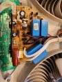
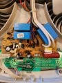
However, I decided to take a look how this board is getting its 5V DC. Here are couple photos of "mains voltage" board:


So tracking back to those two pins, I came up with something like:

I guess it's not important what exact components are those. It seems like "5V DC" is directly connected to AC live. That's nice. And "0V DC" has some kind of capacitor dropper? No idea here. Bunch of zener diodes, transistor, etc. Well it doesn't seem like "clean" DC power that I would like to feed to my arduino. That's bad idea, right?
I'm planning to use small phone charger as 5V power source, and relays to control mains voltage board.
For right now, my components list is:
- Arduino mini
- LCD display
- rotary encoder
- small phone charger
- temperature sensor
- IR receiver (to use remote that came with the fan)
- relay module - found 8 channel ready module on amazon
What you guys think? I know it's quite an overkill, with components' price reaching over price of the fan, but I like projects like that. When I have functioning hardware, I can take care of software no problem.
Plan is to connect arduino with LCD and rotary encoder to make it easy to access options or set temperature.
I will use relays to separate arduino from mains voltage board. I will use some high value resistor to pull up the pins on high voltage board (to that 5V DC), and use relays to pull them down, probably through some lower value (like 1k) resistors. Or maybe it will be better to pull the pins, through high value resistors, to their default states when fan is off?
Did you find any problems with my plan so far?
Couple things to figure out:
- what happens if my arduino code has mistake and for example powers all relays on, pulling all pins down. Will that burn the motors? How can I figure it out?
- current module powers on fan in HIGH mode, and second or two later switches back to selected mode, for example LOW. Would it be a problem if I attempt to start fans directly in LOW mode, or reduce the time of HIGH mode to like 100ms?
Thanks.
I bought Bionaire BW2300-N window fan, which does what it's supposed to, and on LOW setting it's quiet enough to allow me to sleep. However, current fan's controller is quite bad, as it reads temperature all the time, there is no temperature threshold, no delays, and when fan starts, it starts on HIGH and then it goes to option that I set it to.
So for example, fan is set to 60F (minimum) intake on low speed, it turns on in HIGH mode, second later is goes into LOW mode, temperature sensor drops to below 60F and fan shuts down, about 3 seconds later temperature raises above 60F and fan turns ON again. That makes it really annoying and impossible to sleep, and leaving it ON all the time, even on Exchange mode (where one fan blows in, and another blows out), on LOW setting makes whole room too cold.
How to fix that? The plan is to build my own controller that I can program however I want. Because I'm not much of an electronics guy, but I can program without much problems, my best bet is to use arduino. I have some experience with this platform, and connecting it to pre-build modules is fairly easy.
So I begin to reverse engineer current fan controller. It consists of two boards - one mostly mains voltage, and second small board with micro controller or something. Being extremely careful I probed that second board and figured out that it operates at 5V DC. So I disconnected it from rest of the fan, soldered two wires to it, and run it from bench power supply to make it safe to work with (to separate it from any AC stuff).
There is the setup that I used to test that board:
That is what I discovered:
So it seems like it should be really easy to control this fan with arduino.
However, I decided to take a look how this board is getting its 5V DC. Here are couple photos of "mains voltage" board:
So tracking back to those two pins, I came up with something like:
I guess it's not important what exact components are those. It seems like "5V DC" is directly connected to AC live. That's nice. And "0V DC" has some kind of capacitor dropper? No idea here. Bunch of zener diodes, transistor, etc. Well it doesn't seem like "clean" DC power that I would like to feed to my arduino. That's bad idea, right?
I'm planning to use small phone charger as 5V power source, and relays to control mains voltage board.
For right now, my components list is:
- Arduino mini
- LCD display
- rotary encoder
- small phone charger
- temperature sensor
- IR receiver (to use remote that came with the fan)
- relay module - found 8 channel ready module on amazon
What you guys think? I know it's quite an overkill, with components' price reaching over price of the fan, but I like projects like that. When I have functioning hardware, I can take care of software no problem.
Plan is to connect arduino with LCD and rotary encoder to make it easy to access options or set temperature.
I will use relays to separate arduino from mains voltage board. I will use some high value resistor to pull up the pins on high voltage board (to that 5V DC), and use relays to pull them down, probably through some lower value (like 1k) resistors. Or maybe it will be better to pull the pins, through high value resistors, to their default states when fan is off?
Did you find any problems with my plan so far?
Couple things to figure out:
- what happens if my arduino code has mistake and for example powers all relays on, pulling all pins down. Will that burn the motors? How can I figure it out?
- current module powers on fan in HIGH mode, and second or two later switches back to selected mode, for example LOW. Would it be a problem if I attempt to start fans directly in LOW mode, or reduce the time of HIGH mode to like 100ms?
Thanks.