 Facebook
 Google
 GitHub
 Linkedin
Hello everyone, I'm new here! Besides being new *here*, I also happen to be new to electronics. Brand spankin' new. Still in kindergarten new. Anyways, I decided a good, fun project to get to know things a little better, and test the water, would be an LED binary clock. I'm a mechanical engineer, and have been a hobbyist programmer for 8ish years, so thinking technically is no problem for me, so the logic behind the clock should be good. The only problem is, I don't know much about electronics. I still can't figure out how exactly a transistor is used, though I keep hearing it's a switch or an amplifier. Weird. Anyways, not my question.
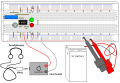
What it all boils down to is this: I've designed a schematic for a binary clock, and I would really, really, really appreciate it if someone could give it a once or twice over, to see if thing will actually work, or the whole deal will go boom in my face. Attached is the schematic.
Originally I was going to do a battery-powered crystal oscillator. But, when I touched that iceberg, I realized that the batteries wouldn't last anywhere near long enough to consistently power 20 LEDs, and to top if off, I couldn't figure out the funky circuits required for it. (Here I was thinking you just threw one in in series and watch it go!). As such, I "borrowed" the 60Hz wall plug idea and schematic from http://www.gimpfaq.org/tutorials/binclock/, as I had no idea how to calculate C1 & C2, the resistor in there, and to use a schotty & zenode thinger. So that goes to that dude, but the rest is from my battery design!
So once again, please, can someone tell me if I'm doing it right? Or wrong? Or am completely nuts? I don't want to just sit around and solder in kits. Those are boring. Plus, I already have one in the mail, but I'm impatient. Also, I can't get this project out of my head. I want to start it right away, and see it through completion. The schematic is in the included pdf.
(I'm using DipTrace free for this, because I found it incredibly easy to use, and the autorouter in it is pretty sweet) (And couldn't find EagleCAD, or any of those other so called "awesome" programs).
Thanks!
Attachments
-
46.9 KB Views: 45
Last edited:


")


