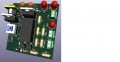
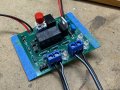
I'm getting 5v output. When the low probe is put in the water the low LED comes on, nothing else happens. When the high probe is put in, nothing happens. When the manual button is pressed, nothing happens. The pump or pump LED never does not come on.
The Kicad checker on both the schematic and PCB came up with no errors. I verified the LED's worked, measured the resistors and checked the manual switch. Assumed other components were OK. Going to dread unsoldering anything. I still have the circuit breadboarded.
In the schematic diagram it looks to me like the diode (D4) across the relay is backwards. That will prevent the relay from operating.
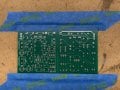
In addition, all of the PCB tracks are very skinny.
In the schematic diagram it looks to me like the diode (D4) across the relay is backwards. That will prevent the relay from operating.
In addition, all of the PCB tracks are very skinny.
Yea they do look skinny. In the PCB editor they did not look skinny, I actually increased them from 10mil to 15mil and had to adjust them. I didn't check how wide 15mil was. This is the first time I had a PCB made from a vendor. I know better now for next time. In the breadboard that sghioto helped me with, the cathode is on pin 16 and that circuit worked as breadboarded. So not sure if i should switch it or not.
In addition to that comment - Q1, when activated by SW1 will be drawing all the raw current to ground (or common as the symbol shows). Q1 may now be blown out.
Yes, they are. And you may have a burned out trace, though that would be easy to find.
SW2 if activated takes power from SW1 to GND. Granted, it's not likely you'll operate both switches at the same time, if Q1 is powered from either SW1 or from the relay itself through D5, what does SW2 do for you? It will ground power. I may be misreading the schematic.
The idea is to switch K1 on when the high water sensor activates it. Once activated it remains held on via the low water sensor. When the low water sensor no longer senses water the relay shuts off and the pump stops running. I'm reading this and ignoring the presence of D4 all together.
Finally, does your pump have three wires? Can you run the pump by hand on the bench by applying power to pins 1 & 2?
The idea is to switch K1 on when the high water sensor activates it. Once activated it remains held on via the low water sensor. When the low water sensor no longer senses water the relay shuts off and the pump stops running. I'm reading this and ignoring the presence of D4 all together.
I suggest that you do not require D4 because Q1 will not switch off rapidly, since C2, 47 mfd, will not allow the base drive to decrease very fast. So there will be no spike voltage produced.
AND the inductive spike is only produced with the fast current drop. Which will not happen.
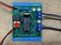
The probes work as they should and the manual switch works. Have to connect SW2 with cables to try that out. The circuit draws 0.194 amps from the power supply when active.
You should make the correction on the schematic referring to D4.
D4 is basically optional but if deciding to use it the schematic should be redrawn correctly. ]
Yes will correct it, and will note that on the schematic.
I have 5 PCB's and enough components now to complete 2. So since this one is working will build a second one, although I need to order a pump. I'll be able to use the spare one in another model.
I started designing the 3D printed bracket for the PCB and pump. Will show that once I'm done. Also have to make the rig for the tubing/wires that extend into the keel.

 Facebook
 Google
 GitHub
 Linkedin