Bifilar coil question

t_n_k

Joined Mar 6, 2009
5,455
OK - then either we are using different inductance values or something else is amiss in the simulations. The other alternative is for me to present a formal solution for the problem which I've resolved and which agrees with my simulation results.

Problem is, given your earlier comments about your math knowledge, you may not be able to assess my theoretical solution anyway.
 

Thread Starter

wes

Joined Aug 24, 2007
242
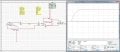
lol probably not. I think I found the reason for the differences though, I was measuring voltage not the current rise time and discharge time, lol, duh.

I have attached picture's showing the waveforms now and they are nearly identical to yours. The numbers seem right on too, there's little differnces but not much.
 

Attachments

Thread Starter

wes

Joined Aug 24, 2007
242
So from this I think what I said earlier that coil B will just either produce a long duration discharge time if allowed to discharge through the same resistance it powered on through is correct. Also it will produce a very high voltage spike if discharged through a higher resistance circuit so the discharge time equals the rise time.

I think these results show that is correct.
 
Last edited:

Thread Starter

wes

Joined Aug 24, 2007
242
Thanks for the link t_k_k, I found the Saturable-core reactors to be very interesting.
Thanks for Bill for the link too, It lead to a lot of other interesting reads


However was there something I was supposed to learn from reading those? Or where they just interesting reads that had to do with things related to bifilar coils. I know the coil I have been talking about isn't exactly a bifilar coil but it still reacts the same way when both coil A and B are powered up in opposing configuration.

Also I never really imagined this coil's purpose would be for transformers or high voltage generators or anything like that. The reason for the separate windings not being connected, wound like a traditional inductance decreasing bifilar coil, is so that each winding can be operated separately (turned on or off etc). The reason for that is an Electromagnet. I have found that for very large Electromagnets like on the order of a 100 Henry's or so, if you needed it to have a rise time of 100 amps in say 1 mS, then it would require a voltage of 10,000,000 volts (10 MILLION VOLTS !!) and then say you leave it on for 3 mS and then discharge it in 1 mS. Then say you wanted to pulse it 100 times a second. Obviously you could never power it with that high a voltage, let alone the power of each pulse would require 1 Gigawatt, you could obviously set it up so once the current reached 100 amps the voltage would drop to whatever was needed to sustain it though. But still 100 Pulses a second, each requiring 1 Gigiawat of power for 1 mS is a lot of power. I think it would be overall be something like 100 Million watts since each pulse is 1 mS and there are 100, that would mean they all add up to 1/10 of a second.

So the reason I had in mind for the bifilar was so it decreased the inductive effects of the 100 henry coil so it would require much less voltage to get it to 100 amps in 1 mS. However since they cancel each others fields that means this electromagnet while big, can't really generate any force to pick something up. So that's why I figured you then just shut down Coil B so that coil B is no longer opposing Coil A's field. This means that now Since Coil A is the only one on, it can now generate large forces unlike before. Granted Coil B will generate a large Inductive spike in coil A but you would have some sort of circuitry in place to cancel that out so it doesn't change Coil A current, since if it did that would mean now since coil A is now going to have rather large inductive effect's, it's current would take way way longer to rise back up to it's previous level. So that is why i figure it is better to just cancel out the inductive effect from coil B effecting coil A's current.


Granted I have no purpose or can even think of one why you would need a electromagnet that big and pulsed that fast (actually that's not very fast, lol ), but it is still a very interesting thing to work on for fun and figure out how you would operate and build it. I mean heck, scale the inductance to like 1000 henrys and you can see how big an issue it is. Maybe someone could tell me what the use for something that big and pulsed like that would be if any as well as the smaller 100 henry or so electromagnet? I know a junkyard magnet isn't one of them, lol.
 
Last edited:

t_n_k

Joined Mar 6, 2009
5,455
Up to this point I've resisted the temptation to question your reasons for raising this question. What you are now asking is way outside my experience. I would make another point concerning your concept of charging & discharging your proposed coil arrangement. With the initial starting condition of driving both coils with flux cancelling currents you are only charging the leakage inductances - not the mutual inductance. What you regard as the discharge phase is in reality a charging phase where the mutual flux is increasing - not decreasing.
 

Thread Starter

wes

Joined Aug 24, 2007
242
If I understand you correctly, then the part about increasing mutual flux being a charging phase is exactly what I figured would happen since coil B is decreasing at some rate (whatever that is depending on many things). I just forgot to put that in there, oops. The way I see it is that as coil B is decreasing, it's magnetic flux that is canceling out coil A's flux is also decreasing. This means that coil A's magnetic flux would be increasing which would be regarded as a charging phase atleast for Coil A, well actually the increasing mutual flux would induce a voltage on coil B aswell. The thing I am not sure of or know about is how long will it take Coil A's magnetic flux to reach steady state (the point at which it is no longer increasing) , also what effects will this have on Coil A's current which up until coil B discharges, it was constant at 100 amps.

One idea I have about what might happen on coil A is coil B will induce a voltage spike on coil A when it discharges, but at the same time since coil A's magnetic flux is increasing (or the mutual flux since they are linked, just Coil A is the biggest source of it and eventually the only) while B's is decreasing. So the increasing mutual flux will induce a voltage on Coil A as well since it is increasing and also on coil B since it see the same flux. I think the induced voltage from the change in the flux would also be in phase with the the voltage induced from Coil B, so they would add.

If this is right then what voltage would the Mutual flux induce on Coil A? If I am assume the time taken for the flux to reach it's steady state value is the same as coil B's discharge time, then since the change in the mutual flux will go from a very tiny value to a huge value in such a short time, then the induced voltage from the increasing mutual flux will be an insane amount. Since we are talking a very very big electromagnet (inductor), the flux value will ultimately be way into the Tesla range.
 
Last edited:

t_n_k

Joined Mar 6, 2009
5,455
Unfortunately - again too many words for my liking. I prefer to cut to the chase.

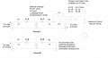
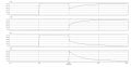
In reality, you would get almost exactly the same current response [save for the initial "instantaneous" downwards step] on Coil B if you simply terminated coil B in 10Ω and applied the 10V source in series with Coil A and its 10Ω series resistor.
 

Thread Starter

wes

Joined Aug 24, 2007
242
I assume your talking about the circuit I showed in the pictures right?
If I understood that, right, your saying that basically, by applying coil B's 10 V source in series with Coil A's when Coil B discharges, Coil A would stay roughly constant? I actually tried a circuit like that, except I just used a current source in series with the 10V source on coil A, The current stayed constant when Coil B discharged. The current source just matched whatever voltage was need which at max was just about 10 V.
 

Thread Starter

wes

Joined Aug 24, 2007
242
I was thinking about what happens when coil B discharges. Since the mutual flux actually increase's when Coil B discharges as you have said before.
Then I would think that by increasing the resistance and decreasing the time constant, the resulting increase in the mutual flux would just happen that much faster.Does the circuit I have been testing take that into account? It seems like it does, but I am not sure?


If so then it seems you should be able to get a big inductor (100 Henry's or so) to say 1 amp faster then if powered up with out the bifilar configuration (once you discharge Coil B of course). Once you discharge coil B, you would just have to stop the voltage spike from effecting Coil A's current.
 
Last edited:

t_n_k

Joined Mar 6, 2009
5,455
I've attached images of the distinction I was making in my last post. I've shown two circuit options and the corresponding current plots. You'll hopefully note that from the 10msec point onwards there is essentially no difference in the resulting coil B current.

On a more general summation:

It seems to me that you are proposing a concept in which one might more quickly energize an inductor.

My understanding of your comments thus far is that the bi-filar idea allowed you to quickly get current into the windings from which you could later recover energy at a slower rate - you called this recovery phase the "discharge". As I pointed out the mutual inductance wasn't actually being charged at all - only the leakage inductance was initially charged. It's not until the secondary coil B is isolated from its source that the mutual flux actually builds up to a steady state value. The "end point" of the maximum possible charging condition would be where the coil B current actually falls to zero and / or coil A current stabilizes to its final value. At this point you could potentially recover energy from the charged mutually coupled system by disconnecting the Coil A supply.

A practical example of this mutual flux charging [but not using bifilar windings] is the automotive ignition coil. Voltage is applied to the low voltage [e.g 12V] DC side of the ignition coil. The high voltage secondary side is effectively open circuit. Current flow in the DC side charges the coil with mutual flux. At the appropriate point in the ignition cycle the low voltage primary side is disconnected and the available energy stored in the mutual flux field is transferred to the high voltage side spark-plug arc.

You are now asking whether one could somehow get energy more rapidly into the inductor [100H say] by increasing the resistance. You suggested getting a 1A target current into the inductance. Suppose you started with the 10Ω resistor. To get to a steady-state current of 1A you would need a 10V DC source. The maximum time taken to charge the inductance would be notionally 5 time constant or 50 seconds with the 100H inductor. Suppose you increase the resistance to 100Ω. You would now need a 100V DC source to do this but you would charge the inductor in about 5 seconds. So yes you can charge more quickly provided you use a higher voltage source.

In the end it comes down to certain laws of physics - you can't instantaneously charge an inductor. The fact that you got current into the coil windings more quickly by contriving to have flux opposing currents flowing in the two coil halves didn't mean you had charged the coil with mutual flux. There's always a penalty to pay in getting the energy into a system more quickly - such as having to apply a bigger voltage to achieve the same outcome.
 

Attachments

Thread Starter

wes

Joined Aug 24, 2007
242
You are correct that I am proposing a way to more quickly energize an inductor (I figured it would be an electromagnet that would push or pull something). However I am not trying to extract any energy back out slower or faster, the goal for this is so you can charge a large value inductor much quicker then if charged up without the bifilar. The end goal for the system is so you can use the resulting flux to do work like push something or pull something. The reason for the bifilar is just so you can get the resulting large flux much quicker than if powered up normally after Coil B discharges of course. Also since when coil B discharges, Coil A's current will already be at the value you want, so the only thing you have to do is counter the voltage spike from coil B. This way you no longer need to supply power to change the current, it is already at the value you want it at, just the flux isn't there yet.

The part about the resistance was about Coil B only (the one that discharges). By switching coil B to a higher resistance discharge circuit, it would discharge much quicker but the voltage spike would be bigger as well. The point of this was so the Mutual flux would build faster.
 
Last edited:

Thread Starter

wes

Joined Aug 24, 2007
242
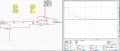
I posted a circuit picture that shows what I mean about using a current source to keep the current in coil A constant when Coil B discharges. The bottom graph is the oscilloscope across the current source. It reaches a max of about 10 V when coil B discharges. This way you don't have to wait for Coil A's current to rise back up.
 

Attachments

t_n_k

Joined Mar 6, 2009
5,455
Dealing firstly with increasing the "discharge" resistance on the coil B side rather than the coil A side. Yes this will reduce the mutual flux charging time of the system. One could increase the coil B "discharge" resistor to infinity - an open circuit - which would give the minimum mutual flux charging time, & which essentially negates any justification for having the coil B side power source in the first place.

Regarding the introduction of the series 1A current source. Adding the ideal 1A current source to the primary is somewhat of a conceptual "trap". As I understand the situation, closure of the J3 switch to complete the primary [coil A] loop commences the injection of current into coil A. Firstly, the presence of the pulsed DC source V1 becomes redundant as the coil A loop current will be solely determined by the ideal 1A current source. Secondly, the presence of any coil A leakage inductance would mean coil A would resist any initial rise in current. The ideal current source terminal voltage would therefore rise to an infinite output value as it attempts to drive the 1A into the leakage inductance. You would see this "problem" in the simulation if you bring the simulation time step down to very small increments. The addition of the current source also flags some support for my earlier comments about having to add additional driving source potential energy to increase the rate of rise of mutual / magnetizing flux.
 
Last edited:

Thread Starter

wes

Joined Aug 24, 2007
242
well the current source was used only when the current was already at 1A, I started the circuit with both sources switched on.


However I did have an idea about what you said earlier about

In the end it comes down to certain laws of physics - you can't instantaneously charge an inductor. The fact that you got current into the coil windings more quickly by contriving to have flux opposing currents flowing in the two coil halves didn't mean you had charged the coil with mutual flux. There's always a penalty to pay in getting the energy into a system more quickly - such as having to apply a bigger voltage to achieve the same outcome.
You see I think what happens is that whether you discharge B and let Coil A's current decrease then rise back up putting energy into the resulting larger magnetic flux or you use a current source to create the voltage's necessary to cancel the effect of the induced voltage from Coil B decreasing Coil a's current while energy is being put to into the magnetic flux. What happens is that in either case, the amount of energy used is = and not only that, but it is equal to same amount of energy you use if you just charged up eithier coil A or B as separate inductors not linked together.

In either case then energy required to build the magnetic flux to certain value is =.


So is the true.
 

t_n_k

Joined Mar 6, 2009
5,455
In principle you seem to have understood the issues. Regarding the energy balance issue for the source (or sources) driving the coil magnetization - the resultant stored field energy isn't the same as the total delivered source energy, since there would be energy losses in the resistances in series with the windings. But I guess you appreciate that matter as well.
 

Thread Starter

wes

Joined Aug 24, 2007
242
Yea I know that any power loss to the resistance isn't going to be stored in the field.

On the subject of getting a large coil (like 100 Henry or any inductance value actually) to charge up faster (smaller time constants), do you know of any way to accomplish that? I know you can't put the inductor into resonance with the appropriate capacitor because while the reactance's cancel, the inductor will still take the same amount of time to charge up to say 1 amp as if it was not in resonance. I already know you can just increase the voltage as well as increase the resistance. Obviously the bifilar idea won't work. So is there a way to get an inductor to charge up faster other than the ones I already stated?


Thanks for all the help.
 

shortbus

Joined Sep 30, 2009
10,049
You could do like they do on some motor windings, its called "two in hand". A form of the bifilar winding. Instead of a single wire of 'x' gage two wires of 1/2 'x' diameter are wound at a time. This gives two paths for a faster voltage rise. It can even be done as three or more in hand, whatever it takes.
 

Thread Starter

wes

Joined Aug 24, 2007
242
Could you explain the two in hand a little more, I don't really get what you mean by "This gives two paths for a faster voltage rise. It can even be done as three or more in hand, whatever it takes.), maybe I will later when I reread this again but I don't get what you mean.
 
Top