Bifilar coil question

Thread Starter

wes

Joined Aug 24, 2007
242
THE BIFILAR COIL IS COMPOSED OF 2 TWO SEPARATE WINDINGS
NOT JUST ONE WOUND AROUND THE CORE THEN BACK AGAIN!!!!

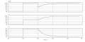
I PROVIDED A PICTURE TO SHOW WHAT I MEAN
The current flow is conventional flow (+ TO -)


Hi, I know bifilar coils are supposed to decrease the inductance of a coil because the windings are wound in such a way as to cancel the each-others magnetic field. The question I came up with though is what happens when one of those windings is shut down (stop powering them and allow them to discharge through say a resistor?

The reason I ask this is because normally when a coil is shut down, it will take a certain amount of time to do so. So if say a 1H inductor takes 1 second to reach steady state at 1 volt, then as long as the circuit is kept the same (resistance) the discharge to steady state will be equal, takes 1 second to discharge with a voltage spike of 1 volt.

But when wound as a Bifilar coil, both windings counteract each other. So that same 1H inductor will now be a 10 uH inductor (I am actually not sure how much the inductance will decrease). Now when you apply power to the both coil A and B of the normally 1H inductor, it acts like a 10 uH inductor and each winding rises to steady state in 10 uS with an applied 1 Volt. So what happens when you discharge only say coil B and leave coil A on at steady state? Wouldn't Coil A now become a 1 H inductor since Coil B is no longer there to counteract coil A's magnetic field?

I know that Coil B will cause a voltage spike on A causing a decrease in the current on A but you could counter act that by powering coil A with a current source so it applies whatever voltage is necessary to keep the current on coil A at a specified level.

I guess what I am trying to get at is what effects does coil B shutting off have on coil A. Coil B's magnetic field will decrease while at the same time Coil A's magnetic field would rise to become the only magnetic field in the coil. orginaly they were say 10 uH becomes of the opposition of each-others magnetic field but now with coil B, Coil A now acts like a 1 H inductor?
 

Attachments

t_n_k

Joined Mar 6, 2009
5,455
Bifilar windings reduce leakage losses in the mutual inductance between the windings - not the individual winding self inductances. In other words bifilar wound coils have an improved coupling coefficient between the coils / windings.
 

Thread Starter

wes

Joined Aug 24, 2007
242
wait what? umm maybe I worded it wrong then, what I meant by when I said

So that same 1H inductor will now be a 10 uH inductor (I am actually not sure how much the inductance will decrease). Now when you apply power to the both coil A and B of the normally 1H inductor, it acts like a 10 uH inductor and each winding rises to steady state in 10 uS with an applied 1 Volt. So what happens when you discharge only say coil B and leave coil A on at steady state? Wouldn't Coil A now become a 1 H inductor since Coil B is no longer there to counteract coil A's magnetic field?
was that when the coil is wound normally it is a 1H inductor, but in bifilar winding it is 10 uh (again just threw this number out there). Maybe I made it seem that both coils were 10 uh, sorry. So both COIL A and B are part of the same inductor. I guess since each Winding is technically half the total inductors total number of windings, that means COIL A and B are half the 1H, so .5H . When they power up at the same time, they oppose each-others magnetic field and so COIL A and B act as if they were smaller inductors since they are each seperate windings.
 

Thread Starter

wes

Joined Aug 24, 2007
242
I guess in short I am trying to get too is what happens when you power up a bifilar coil in opposing mode so the 2 windings oppose eachother. Since they oppose that means it will act as if it was a smaller inductor even though it is still same amount of windings. So what happens when you shut one of those windings down. If you shut say B off and A is still on, then A is now going to act like a much bigger inductor since B is not there anymore to oppose A's magnetic field. So what happens to A since B will induce a voltage in A to try and reduce the current in A, but at the same time, A's magnetic field is expanding and becoming stronger since the current on A is already at steady state, before B effects A's current. Not to mention that A's inductance, normal inductance when B is not on, is potentially many many times higher.
 

t_n_k

Joined Mar 6, 2009
5,455
I get your point now. You seem to have a grasp on the overall issues involved. Certainly the effective initial inductance seen by the driving source with the coils connected in (flux opposing) anti-parallel configuration would be small - in fact zero for an ideal mutually coupled arrangement.

The solution to the circuit behavior after one of the coils is isolated is somewhat complex owing to the mutual inductance between the two coils. I can derive the equations which would resolve the circuit conditions [after the second coil is isolated] for a specific circuit arrangement. I'm not sure if you are actually interested in such a solution or only interested in the general physical concept of what might occur. Perhaps you could solve this yourself as a challenge problem.
 

Thread Starter

wes

Joined Aug 24, 2007
242
I am not sure how to even solve it, lol. I am really just interested in the overall physics of what will happen though. However I would still like to know how you might go about trying to solve this. Just FYI, I don't know calculus or any even trigonometry that well, lol. I am learning though, I have been using Khan Academy, lol.
 

t_n_k

Joined Mar 6, 2009
5,455
Rather than providing a complicated mathematical solution I've attached the results of a simulation of a possible implementation of your "experiment".

The two attachments show firstly the simulation schematic with brief comments regarding the proposed operating circuit conditions and secondly the current responses at three key points.

One can readily observe the rapid rise of current (at 1.5 sec) with the two windings connected in flux opposing mode. With the second winding isolated (at 2 seconds) and discharged through a resistor, one can also see a significant time constant controlling the response.
 

Attachments

Thread Starter

wes

Joined Aug 24, 2007
242
So if I am understanding this correctly then what is happening is that when both coil's are turned on, they oppose and thus rise very quickly. When Coil B is shut off it would seem that coil B discharges at a rate that it would normally discharge at if it was just by itself. The reason I believe is that there is no opposing magnetic field changing to cancel out Coil Bs back-emf. If Coil A were to discharge at the same exact time then I would think the current in both of them would drop at the same rate they powered on in

This I think actually makes since, since A is no longer changing and is at steady state, then any change B makes is no longer canceled out by A and thus B acts as a ,much larger inductor because of this.

So going back to the numbers I threw out, lol.
plus time this time, lol.

When turning on they oppose and act like 10 uh inductors.
They rise to steady state in 1 second.
This requires a voltage of 0.00001 Volts

When B turn's off by say connecting to a discharge circuit so that it discharges in the same amount of time it took to turn on. Coil B discharges as a 1 H inductor in 1 second.
This causes a 1 volt induced on B itself as well as A
The voltage induced on A acts to decrease the net voltage and thus cause a current decrease.

However since these voltages are so low, I am pretty sure you could set up a current source on A to counteract the induced 1 volt from B.

I am thinking that the cancellation of there magnetic fields is not necessarily the reason why bifilar's work the way they do, well not directly. Just like how you were talking about how mutually coupled they are, I think that is the direct cause for the cancellation of there inductance's because the better coupled they are, the better there induced voltages to counteract each coils back-emf. The Opposing magnetic fields is just what is needed to cause the opposing voltages to each-others back-emf. I use to think it was the magnetic fields flux strength and since both were opposing they canceled the flux produced from one another and so that was the reason for lower inductance. But now I see that the flux cancellation is more a side effect and it is just what is needed to cause the induced voltage in such a way as to cancel each-others back-emf. It also just happens that because of the flux canceling, they can't store as much energy in the flu


So did I understand that correctly, lol.
How far off is my reasoning for it?
If I am far off then what really happens?
 

t_n_k

Joined Mar 6, 2009
5,455
So if I am understanding this correctly then what is happening is that when both coil's are turned on, they oppose and thus rise very quickly.
True

When Coil B is shut off it would seem that coil B discharges at a rate that it would normally discharge at if it was just by itself.
Not necessarily true - there is interaction with the other coil by virtue of mutual inductance. If a current path exists for mutually induced current to flow in the other coil [as shown in my example schematic] then the time constant depends on parameters on both "sides" of the mutually coupled coil.

Coil A were to discharge at the same exact time then I would think the current in both of them would drop at the same rate they powered on in
True

So going back to the numbers I threw out, lol.
plus time this time, lol.

When turning on they oppose and act like 10 uh inductors.
They rise to steady state in 1 second.
This requires a voltage of 0.00001 Volts
Your argument is rather ambiguous here. What do you mean by steady state?

Trying to reason the physical behavior purely by words is too cumbersome for me. Following through a rigorous analysis is probably important at some point in understanding what is happening at any instant of time. It also helps to base one's arguments around a particular schematic. As I indicated above, the resulting circuit conditions can vary according to how things are "connected" in practice.
 

Thread Starter

wes

Joined Aug 24, 2007
242
When I say steady state, I mean the point where the current is no longer changing. Like going from 0 to 1 amp, once the current reaches 1 amp, it is steady and not changing anymore.

When ever I have been thinking about it, I think of it as the two coils are not connected to each other, rather each are driven by there own separate circuit.

Like in the image I attached, each coil is wound on the same core and then powered by there own circuitry. Both circuits are in no way connected to one another other then through the mutual inductance of the two coils.
 

Attachments

t_n_k

Joined Mar 6, 2009
5,455
You need to justify that reasoning somewhat. What limits the current to 1A?
If (say) an ideal DC voltage source is applied to either winding with zero resistance the current would increase in an unbounded manner - irrespective of the effective inductance.

Again I stress the need to think of a specific circuit configuration which is at least theoretically consistent with a plausible physical result.
 

Thread Starter

wes

Joined Aug 24, 2007
242
I guess I will try to design a circuit in a circuit simulator and see what you think. I figured the current would be limited by a resistor or something, maybe a current source that would vary the voltage needed to keep the current constant.
 

shortbus

Joined Sep 30, 2009
10,045
Its always been my understanding that a bifilar wound inductor is a single winding doubled back on its self. By that I mean - say the length of conductor needs to be 2m, you would fold the wire in half and then make the coil. One wire in and one wire out.

With two separate windings, having different polarities wouldn't you have the same thing as a 1:1 transformer out of phase? Unless you have an AC voltage or a square wave DC on this winding there will be no inductive link to the separate coils.
 

Thread Starter

wes

Joined Aug 24, 2007
242
Well I have been testing with this circuit that I attached. It's just a simple circuit I made to test it.

The Transformer is my bifilar coil.
Each winding is 10 mH
Coupling coefficient is .995

The way it works is both square wave sources are on at the start of the Sim and stay on until the end (I should have just used a DC source, but I am tired and going to go to bed after this, lol). One is at 10V and the other is -10V

I use two switches to control when the coils of the transformer are turned on.

The Right side coil is supposed to be like Coil B I have been talking about which shuts down.

So after the sim is started I hit the switches and you can see on the oscilloscope the Voltage rise's and falls back down very quickly since the current increases very quickly. You can't actually see in the image but it does. The rise time if I am correct correlates to that of about a 25 uH inductor. I calculated that by first measuring the highest point of the voltage spike, then figured out what 63% of that was. I then just had to measure the time between 0 and 63% of the voltage spike which was right around 2.5 uS. Then using the equation for T=L/R time constants, I just rearranged for L= TR which gave me about 25 uH.

Next after about 50 mS I switched Coil B to the discharge circuit which discharge's it through the same resistor of 10 ohm. As you can clearly see, coil B behaves as a normal 10 mH inductor, I calculated this the same way I calculated the inductance for the rise time. Also coil A (left side) has the same induced voltage spike as coil B since the coupling coefficient is so high, you can't see it though.


I don't know if I am forgetting something, I have been up nearly 24 Hours so far, lol. From what I can tell though, when coil B shuts down, it behaves as a normal 10 mH inductor, which means when discharged through the same resistance, it will take substantially longer to reach 0. On the other hand if the discharge circuit was built in such a way as to keep the discharge time the same as the rise time then the voltage spike would be substantially higher. Also Coil A would experience either the Higher voltage spike or the longer duration voltage spike as well.

So does this seems about right?
If not, then what is wrong?

p.s. The circuit is just built to test for what happens, so a lot protective devices and such aren't in there.
 

Attachments

t_n_k

Joined Mar 6, 2009
5,455
Its always been my understanding that a bifilar wound inductor is a single winding doubled back on its self. By that I mean - say the length of conductor needs to be 2m, you would fold the wire in half and then make the coil. One wire in and one wire out.

With two separate windings, having different polarities wouldn't you have the same thing as a 1:1 transformer out of phase? Unless you have an AC voltage or a square wave DC on this winding there will be no inductive link to the separate coils.
I've actually wound a bifilar pulse transformer years ago. The goal was to minimize the leakage inductance.
 

Thread Starter

wes

Joined Aug 24, 2007
242
lol yeah it's only purpose was so that the circuit was off when the sim started, When J3 is off, J1 is switched to the discharge circuit so that coil B is off as well. When the sim starts I hit space and it switches both switches simultaneously so that J3 is now on and J1 is switched to the power on circuit.

You can see on the oscilloscope when I switch them, it's the little thin red line.

Then after about 50 mS I switch J1 so coil B discharges and you can clearly see that on the oscilloscope. You can see that when coil is switched off it discharges as a normal 10 mH inductor,
 

t_n_k

Joined Mar 6, 2009
5,455
Since both J1 & J3 are controlled by the same key [space bar] I presume J3 also disconnects the other side of the coil when you switch J1 to the discharge condition. So the other side of transformer is also turned off to an open circuit.

That's why you see only the equivalent 10mH time constant. If the primary side was left powered on you would see twice that time constant since the resistance determining the time constant would be the parallel combination of the primary and secondary resistances - 5 ohms in this case.

Opening the primary side [after charging] also represents an invalid condition because the primary leakage inductance has a current switching from a finite to zero value instantaneously which would notionally cause an infinite emf across the primary leakage inductance.
 

Thread Starter

wes

Joined Aug 24, 2007
242
Actually I only hit space bar once to turn them on (the switches), I then manually click J1 to switch it from the power source to the discharge circuit. Once J3 is switched on, i don't switch it back. Only when I reset the sim I switch it back to off.
 
Top