 Facebook
 Google
 GitHub
 Linkedin
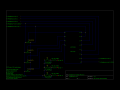
Hi all, this is my first post and I am currently in need of some help. These are probably easy questions to answer but I just need some reassurance that I am on the right path. So I am soldering my first perfboard and I am following this schematic attached to this post.
For the rpieffectboc.png schematic I am just confused with this whole thing. I understand whats going on to a bare minimum. What throws me off are all of the wire connections like the two at the top left. How do I go about connecting two wires while also having go into a different direction like he does for "To raspberry pi pin 6 (GND)". I can't picture what that looks like. Is it three wires? Also how do I know which color wires to use? I bought this pack of wires from radioshack and I am not really too sure if these are the right wires for perfboards
http://www.radioshack.com/75-ft-ul-recognized-hookup-wire-22awg/2781224.html#q=wire+red+green&start=4
Thanks for your help if you can help guide me in the right direction. I am working on this project and I kinda need it done by the end of the weekend
Attachments
-
 58.5 KB Views: 51


