Beginner, making series/parralels

Thread Starter

dukebdx12

Joined Jan 29, 2008
30
http://i186.photobucket.com/albums/x207/dukebdx12/ecehw2.jpg

- R11 and R12 are supposed to be 100 not 1k.

I want to see if I have done this right. I was to draw 2 circuits A and B. with A having 4 100 Ohm resistors to realize an equivalent resistance of 250 Ohms. And B having 4 100 Ohm resistors to realize an equivalent resistance of 75 Ohms. Please correct if I have messed up. I am trying to learn. I also have to explain my work for park A and B and explain how I used the equations for the equivalent value of resistors in series and resistors in parallel to obtain 250 Ohms and 75 Ohms. I will try to start on that later after I have figured out the drawing first.
 

beenthere

Joined Apr 20, 2004
15,819
There is no difference, except for component location, between the two drawings. Hopefully, you're not just fishing for an easy answer.

Start with a a voltage source and ground. Place resistors in one at a time, and determine the total resistance. It's pretty easy to see what the combination of any two resistors is. Problem A should take no time at all if you just take the time to do the calculation. B will become obvious as soon as you have A.
 

Thread Starter

dukebdx12

Joined Jan 29, 2008
30
There is no difference, except for component location, between the two drawings. Hopefully, you're not just fishing for an easy answer.

Start with a a voltage source and ground. Place resistors in one at a time, and determine the total resistance. It's pretty easy to see what the combination of any two resistors is. Problem A should take no time at all if you just take the time to do the calculation. B will become obvious as soon as you have A.
wow. strong opinion. Did you not read the title of this thread stating "BEGINNER"? if not then now you know. This is my first assignment in this class that I really knew nothing about.
 

Thread Starter

dukebdx12

Joined Jan 29, 2008
30
yes i know how to calculate it. I have figured out A and I have it right with 2 series and 2 parallels. For B I need 3 series and 1 parallel which will = 75 but I'm having trouble setting it up.
 

JoeJester

Joined Apr 26, 2005
4,390
You need to start with the measuring points and then add the resistors as needed. Convert your words to a schematic. Then post the schematic.
 

conehed

Joined Jan 9, 2008
11
two in parallel will give you 50 Ohms then add it to 2 100 resitors in series......

(100x100)/(100+100)=50

put that in series with the 2 other resistances= 250 Ohms

sorry cant show a diagram because i cant upload word docs

hope that helps
 

Dave

Joined Nov 17, 2003
6,969
sorry cant show a diagram because i cant upload word docs
You can. In the post reply screen, scroll down to the "Additional Options" section and select "Manage Attachments" - you can upload several file types from there, one of which is Word (.DOC) documents up to 2MBs.

Dave
 

Thread Starter

dukebdx12

Joined Jan 29, 2008
30
http://i186.photobucket.com/albums/x207/dukebdx12/series_parallelcircuits.jpg

here i have posted a link of what i got.

Park A i needed to use 4 resistors each 100 Ohms to get 250 Ohms. My equation is R2 and R3 are parallel which gives me 50 and R1 and R4 are series with R23 which will give me 250 Ohms. Please correct me if I'm wrong.

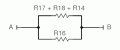
Part B i needed to use 4 resistors each 100 Ohms to get 75 Ohms. I'm not sure what to do on this one but I put together something thinking R17, R18, R14 are series which gives me 300 and R171814 are parallel with R16 which then will give me 75. I'm not sure if I set this one up right so could someone help me on this a let me know if I need to change something.
 

JoeJester

Joined Apr 26, 2005
4,390
Part B, according to your diagram is 300 ohms.

You shorted out R15.

For B I need 3 series and 1 parallel which will = 75 but I'm having trouble setting it up.
What is that 1 resistor in parallel with? If you worked it out mathematically ... you should be able to draw it.

If you can't put up the drawing, put up the math.
 

Thread Starter

dukebdx12

Joined Jan 29, 2008
30
Part B, according to your diagram is 300 ohms.

You shorted out R15.


What is that 1 resistor in parallel with? If you worked it out mathematically ... you should be able to draw it.

If you can't put up the drawing, put up the math.
and why is that? this is my first project in this class and i need a little help. By my math i need 3 series and 1 parallel for it to = 75 omhs but I can't seem to figure how to make it. My math was say I have 4 resisters R1, R2, R3, and R4. I take the series to = 300 omhs and parallel with R4 to = 75. Have I done something wrong with that? I'm assumming I got Part A right with it equaling 250 ohms?
 

JoeJester

Joined Apr 26, 2005
4,390
I have a difficult time understanding how you can "get the math" yet not correlate that to the schematic diagram.

You said exactly how you wanted to do it ... and you were correct.
 

Attachments

Top