Battlestar Galactica Cylon Eye Circuit

Thread Starter

Kim Sleep

Joined Nov 6, 2014
426
that is two different circuits... you mean to use one on the right, this is it.

note that it is not complete. you need to add into schematics diodes CR11-CR32
basically each output on U6 and U7 has two diodes (OR circuit).
so you need to follow the pattern that is started and add rest of the diodes yourself.
i added couple more in case you did not catch on what the pattern is.
U2 and U3 are moving eye in one direction (down). when their output is set, diodes activate corresponding U6/U7 channel.
then you have U4 and U5, they also run in same direction (down) of course but their outputs (via diodes) are wired to U6/U7 channels in reverse order (up), making it look like eye is moving in the reverse direction.

good luck with 70s electronics.

View attachment 369255
and if I want more outputs to a total of 32??
 
and el cheapo unit like RP has two cores, it can easily do voice change too thanks to I2S interface. for example using ICS-43434 or INMPL441 microphone and 3W amp (MAX98357A)

1783538643796.png
1783538717495.png
1783538759138.png
 
and if I want more outputs to a total of 32??
you need to keep cascading those counters (4017), you will need total of 8 of them (each 4017 can do 10 states) and you will need more diodes and more ULNxxxx ICs. actually last output of one 4017 is not usable for LEDs in this case because it is a 'handshake' signal to rest of counters. so you get 4 ICs x9 states gives you max 36 channels. then you have to double it for reverse.
you should really consider how to route all that. wiring will be mess even with the just 16 channels.

in comparison, modern version using MCU and addressable LEDs, one can get long enough LED rope, cut it to whatever length is needed and that is the only hardware change. all wiring stays the same. in fact you can connect more than one rope and make this run around swimming pool. 16 or 32 or 3200 LEds makes no difference.
 
Last edited:
Just a thought: could the leading and trailing effect just be light bleeding from a single active lamp? I suspect the prop makers did it the simplest way possible. Up/down counter and a couple of 74154 or something similar?
 

joeyd999

Joined Jun 6, 2011
6,360
Just a thought: could the leading and trailing effect just be light bleeding from a single active lamp?
That's part of it -- LEDs tend to be more of a point source than incandescents. But incandescents heat and cool (relatively) slowly, giving a soft on/off that LEDs lack -- along with a warm color.

These days, the effect can be simulated quite well with software and the appropriate hardware.
 

AnalogKid

Joined Aug 1, 2013
12,181
I know this is heresy, but the AI information in post #1 might not be accurate.

A significant difference between a Knight Rider circuit and a Cylon circuit is the brightness of the bulbs ahead of the "main" bulb being lit at full brightness. In a Knight circuit, the bulb immediately ahead of the bulb being lit is dark. In the post #36 video, it is clear that at least two of the bulbs ahead of the main bulb are lit dimly. Watching YouTube clips slowed down to 25%, it looks to me like there is a five- (or more) bulb traveling pattern, so the scanner looks like a moving ellipse with a fade-up leading edge and fade-down trailing edge, rather than a circle with a tail. Bloom from the brightness of the main bulb makes the sensor look more like an ellipse than an oval.

This means that more bulbs are at least partly on more often, a significant increase in heat load. The original Knight device looks like automotive turn signal or brake bulbs known for their large photonic lag time, so they got the trailing tail for free.

How many lights (steps in the pattern) are you trying for? If I'm right, you're looking at three or more drive transistors per bulb.

ak

Update: Screen grab from post #36.

1783619986565.png

In this image, the sensor is moving from left to right. Panic might be righ about light bleed, but there is a clear trailing tail extending behind the sensor to the left that is not extending ahead of the sensor to the right.
 
Last edited:
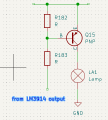
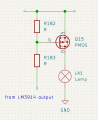
i thin the light bleed through was due light bulbs being encased in resin. but one should be able to simulate that by placing resistors from one output to the next on driver chip (such as LM3914). they will form voltage dividers with nearby channels. with that, single transistor per output is needed.
 
Last edited:

panic mode

Joined Oct 10, 2011
5,098
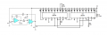
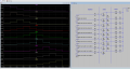
this is an example of what i meant by adding resistors across channels (in this case R1-R11) in #57.
result is similar to using capacitors but it affects both lead and trail edges and it is dirt simple to size and add.

1783689847419.png
 
Top