Battlestar Galactica Cylon Eye Circuit

Thread Starter

Kim Sleep

Joined Nov 6, 2014
427
i doubt it... original helmets should already have the circuitry built in.


where does the idea of incandescent light bulbs come from? the lights are clearly 5mm diffused red LEDs. so much for "authenticity" ;)
Electronics were mostly "stripped out" of the helmets, as the helmets were resold, either because they were no longer working or simply damaged badly. A lot of the helmets were used on the Universal studios, ride in the 80s, and were beaten to death by the wearers during those usages.
 

Thread Starter

Kim Sleep

Joined Nov 6, 2014
427
i doubt it... original helmets should already have the circuitry built in.


where does the idea of incandescent light bulbs come from? the lights are clearly 5mm diffused red LEDs. so much for "authenticity" ;)
lightbulbs take more space, power and would be too hot for wearer.
There are many statements and pictures showing that they were made with incandescent bulbs, 32 to be exact.
I believe that 5mm units will fill the eye slit exactly
 

Thread Starter

Kim Sleep

Joined Nov 6, 2014
427
i doubt it... original helmets should already have the circuitry built in.


where does the idea of incandescent light bulbs come from? the lights are clearly 5mm diffused red LEDs. so much for "authenticity" ;)
lightbulbs take more space, power and would be too hot for wearer.
One of the main complaints of the wearers at that time was that the helmets were incredibly hot to wear. The "Grill " in the front "Mouth" area was Aluminum, and used as a heat sync. The circuits were turned off immediately between takes
 
then get bunch of tiny bulbs in a row, encase them in red resin. resin will make the light bleed through to nearby bulbs that are not on making it wide "smear". instead of discrete transistors, perhaps use ULN2xxx drivers. logic is just shifting bit back and forth.
using LEDs one can simulate "smear" in software.
 

joeyd999

Joined Jun 6, 2011
6,360
One of the main complaints of the wearers at that time was that the helmets were incredibly hot to wear. The "Grill " in the front "Mouth" area was Aluminum, and used as a heat sync. The circuits were turned off immediately between takes
That video was created in 2008, before full-color addressable LEDs were commonly available.

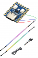
Using appropriate optical materials, I think I could match the original to where you couldn't tell the difference using an LED strip and an MCU.
 
Just an observation.

The video in post 16 shows only a trailing fade but the "original" in post 24 shows both a leading and trailing fade.

I know for me personally, that would be a challenge in software, and the platform I use doesn't have enough analog output pins to make it something simple, not that that would be acceptable anyway.

PWM would be the way to go, but the platform I use has only 4 hardware PWM modules, and the software for creating 6 or 8 PWM outputs at the same time is beyond me. (probably easy for a pro)

And creating both fades in discrete logic would be tough, a simple cap on the base wouldn't cut it.
 
I know for me personally, that would be a challenge in software...
It is trivial in software.

Here's a scanning fade I use in existing code (just a table of values). 17 "frames" indexed by a pointer painting 6 LEDs each frame.

Scanning Fade:
const ws_triled_t ui_pattern_warmup[]=
{
    {.rgb=0x000000}, // frame  0
    {.rgb=0x000000}, // frame  1
    {.rgb=0x000000}, // frame  2
    {.rgb=0x000000}, // frame  3
    {.rgb=0x000000}, // frame  4
    {.rgb=0x000000}, // frame  5 -- EOF  0
    {.rgb=0x040100}, // frame  6 -- EOF  1
    {.rgb=0x0C0300}, // frame  7 -- EOF  2
    {.rgb=0x1C0800}, // frame  8 -- EOF  3
    {.rgb=0x3D1000}, // frame  9 -- EOF  4
    {.rgb=0x7D2200}, // frame 10 -- EOF  5
    {.rgb=0xFF4500}, // frame 11 -- EOF  6
    {.rgb=0x7D2200}, // frame 12 -- EOF  7
    {.rgb=0x3D1000}, // frame 13 -- EOF  8
    {.rgb=0x1C0800}, // frame 14 -- EOF  9
    {.rgb=0x0C0300}, // frame 15 -- EOF  0
    {.rgb=0x040100}, // frame 16 -- EOF 11
    {.rgb=0x000000}, //          -- EOF 12
    {.rgb=0x000000}, //          -- EOF 13
    {.rgb=0x000000}, //          -- EOF 14
    {.rgb=0x000000}, //          -- EOF 15
    {.rgb=0x000000}  //          -- EOF 16
};
 

Thread Starter

Kim Sleep

Joined Nov 6, 2014
427
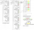
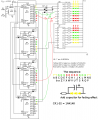
Ok I have decided to use this circuit. The only thing that Im questioning is obviously I will need 2n3904 transistors to drive the lamps, but I dont understand the circuit on the right. I dont follow why the cascaded 4017 ics (U2, U3, U4, U5) have little colored arrows, while u6 and U7 have the outputs driving the leds??????
 

Attachments

that is two different circuits... you mean to use one on the right, this is it.

note that it is not complete. you need to add into schematics diodes CR11-CR32
basically each output on U6 and U7 has two diodes (OR circuit).
so you need to follow the pattern that is started and add rest of the diodes yourself.
i added couple more in case you did not catch on what the pattern is.
U2 and U3 are moving eye in one direction (down). when their output is set, diodes activate corresponding U6/U7 channel.
then you have U4 and U5, they also run in same direction (down) of course but their outputs (via diodes) are wired to U6/U7 channels in reverse order (up), making it look like eye is moving in the reverse direction.

good luck with 70s electronics.

1783537024732.png
 
Last edited:
Top