 Facebook
 Google
 GitHub
 Linkedin
Hello all. My Arduino project requires to be battery powered and have +/-30V and +/-18V rails available for op amps etc.
I was thinking of using a 2 cell LiPo battery that can be recharged over USB/5V wall wart by using this board:
https://wiki.dfrobot.com/USB_Charger_for_7.4V_LiPo_Battery_SKU__DFR0564
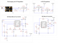
This would give me a 7.4V rail which I would feed through a 7805 regulator to get 5V (and bypass any issues with the battery voltage depleting as it is used). For the 2 pairs of bipolar supplies, I was thinking of using 2 LT1072 switching regulators: one as a boost converter to boost 5V to 30V, the other as a buck-boost converter to convert 5V to -30V. This +/-30V supply would then go through a 7818/7918 regulator pair to give me the +/-18V supply.
The problem I have is in the LT1072 data sheet I can't find any formula to figure out how to get the boosted voltage from 5V to 30V and 5V to -30V. I have attached my schematic. I assume it will have something to do with the ratio of the resistors connected to the FB pin - R1:R4 for the boost converter, R8:R5 for the buck-boost converter...?)
This is my first SMPS design, so if anyone can help me I'd really appreciate it")
I was thinking of using a 2 cell LiPo battery that can be recharged over USB/5V wall wart by using this board:
https://wiki.dfrobot.com/USB_Charger_for_7.4V_LiPo_Battery_SKU__DFR0564
This would give me a 7.4V rail which I would feed through a 7805 regulator to get 5V (and bypass any issues with the battery voltage depleting as it is used). For the 2 pairs of bipolar supplies, I was thinking of using 2 LT1072 switching regulators: one as a boost converter to boost 5V to 30V, the other as a buck-boost converter to convert 5V to -30V. This +/-30V supply would then go through a 7818/7918 regulator pair to give me the +/-18V supply.
The problem I have is in the LT1072 data sheet I can't find any formula to figure out how to get the boosted voltage from 5V to 30V and 5V to -30V. I have attached my schematic. I assume it will have something to do with the ratio of the resistors connected to the FB pin - R1:R4 for the boost converter, R8:R5 for the buck-boost converter...?)
This is my first SMPS design, so if anyone can help me I'd really appreciate it
Attachments
-
184.9 KB Views: 2
-
 56.7 KB Views: 6


