Battery overheating

Thread Starter

Shaggy74

Joined Oct 20, 2017
36
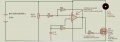
Hi, I have built this circuit, the only change is that I’ve replaced the motor with a 10v shaker motor. My problem is, I’m using a 12v battery but it gets so hot, I was wondering how I can prevent this from happening please? i am very new to electronics so would appreciate any help. Thanks
upload_2018-8-7_5-23-38.jpeg
 

Attachments

MrChips

Joined Oct 2, 2009
34,698
What is the type of battery?
How much current does the motor take?
How long is the motor running for the battery to get hot?
How hot is the battery?
 

Bordodynov

Joined May 20, 2015
3,430
If you have an oscilloscope, then look at what happens at the input of the operational amplifier and the gate of the transistor. Sorry, I'm just too lazy to model your circuit. It's much easier to see an oscilloscope. In addition, there is an urgent need to shunt the motor with a diode!
 

Audioguru

Joined Dec 20, 2007
11,248
I have a Ni-MH rechargeable AAA battery that accidently got shorted when it was fully charged. It made so much heat that its label came loose and is all puckered up. This damaged battery cell can only produce a max current of 0.4A but a good one produces 6A.
 

Audioguru

Joined Dec 20, 2007
11,248
Your lousy old LM358 is not suitable to drive the Mosfet. You need a high current Mosfet driver.

The LM358 is VERY slow so instead of making the Mosfet switch on quickly, it is causing the slow ramp shown in the current in L1.
The fairly high value of R4 with the high gate capacitance of the Mosfet is also causing the slow ramp, but the LM358 cannot drive a resistance that is less.

When you add the diode across L1 then all the energy pumped into the inductor is fed to the battery that causes heating when the inductor is charged and when its charge is fed to the battery.
 

Bordodynov

Joined May 20, 2015
3,430
If you do not add a diode to the motor, the transistor will break through and will not be able to work for a long time in this mode. I set the breakdown parameter of 100 volts. It is common practice to use a diode connected in parallel to the motor. You should note that the average current through the motor can be large, but by moving the slider (slider) of the resistor downward, you can reduce the current that I showed. Yes, the resistor in the gate is large, but the frequency of the pulse signal is small, and even if it is made to be 100 ohm, that will change.
In addition to the diode, I would add another resistor, connected in series with a potentiometer (10 kΩ, from above).
2018-08-08_16-08-25.png
 

ebp

Joined Feb 8, 2018
2,332
The first thing I would do would be to put a capacitor of 1000 µF (more or less, according to load current) across the battery. This will reduce the RMS current from the battery and reduce battery heating due to loss in its internal resistance. Note that a capacitor such as this is hard on switch contacts if it is downstream of the switch and puts a small leakage current load across the battery if it is upstream.

Slow turn-on of the FET is largely irrelevant for a load that is dominantly inductive if the inductor is discharged at the start. The ramping rise of current is exactly as expected in an inductor. However, if the inductor is not fully discharged when the FET is off ("continuous" inductor current), then switching loss can be substantial because the inductor forces non-zero current during the switching transition. High gate drive current is then desirable to limit the width of the lossy transition time.

A diode across the inductor does not put energy back into the power supply. It discharges the inductor by "circulating" the current through it, dissipating the energy in the inductor's resistance and the diode's losses. Using a diode in this way greatly slows the discharge of the inductor, but also means that stored energy is at least partially used instead of wasted in the case of a motor.
 

crutschow

Joined Mar 14, 2008
38,407
That’s what I originally thought but when I upped the voltage from a 12v to 10x 1.5v AA it heated up even quicker?
Of course.
From Ohm's law, higher voltage means higher current.
For more battery capacity you go to a larger battery such as a C or D cell, not more voltage.
You shouldn't apply more than 10V to a 10V motor.
 
Last edited:

Thread Starter

Shaggy74

Joined Oct 20, 2017
36
Your lousy old LM358 is not suitable to drive the Mosfet. You need a high current Mosfet driver.

The LM358 is VERY slow so instead of making the Mosfet switch on quickly, it is causing the slow ramp shown in the current in L1.
The fairly high value of R4 with the high gate capacitance of the Mosfet is also causing the slow ramp, but the LM358 cannot drive a resistance that is less.

When you add the diode across L1 then all the energy pumped into the inductor is fed to the battery that causes heating when the inductor is charged and when its charge is fed to the battery.
What would you suggest as an alternative?
 

Audioguru

Joined Dec 20, 2007
11,248
The LM358 was one of the first low power opamps. Then its idle current is low causing crossover distortion and its speed and ability to produce high frequencies is poor. There are hundreds of "ordinary power" opamps that are much faster.

A TLE2141 is a single high speed opamp, a TLE2142 is a dual and a TLE2144 is a quad. They have inputs that work all the way down to ground in your circuit like the LM358.
 

ebp

Joined Feb 8, 2018
2,332
I am unconvinced that the speed of the op amp is of any particular concern. I am, however, convinced that what is needed is RC or diode-capacitor decoupling of the op amp circuit's power from the the battery/load so that gross variation in the battery terminal voltage does not make a mess of the hysteresis (change in battery voltage works in direct opposition to the intent of the positive feedback AND changes the voltage from the pot in the wrong direction). The output of the amp should not be hanging around at 4 volts. The "red" case is not greatly different from the "blue" case - both operate the inductor in continuous current mode. The load on the amp is not substantially different between the two cases, so the long dwell at 4 V can't be accounted for by loading, as far as I can see (but loading doesn't help matters any because if further reduces the positive feedback). What is different is the magnitude of badness power supply.

Using the other amp in the package as an inverting comparator would reverse the action of the speed control pot but should "fix" the interference with hysteresis.
 

ebp

Joined Feb 8, 2018
2,332
A low slewrate and limited drive capability contribute to switching losses.
Sure, but the switching frequency is very low so the average loss is small. But that loss might still be high enough to be of concern and would need to be looked at critically.
 

Bordodynov

Joined May 20, 2015
3,430
As you can see, adding a 1000 uF capacitor and a faster operational amplifier drastically reduced the dissipated power of the transistor (I have Ptr and have this power).
 
Top