Facebook
 Google
 GitHub
 Linkedin
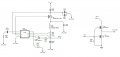
I have built a battery charger using the LTC4002.
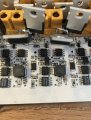
I am having problems with the P- MOSFET and diodes overheating and eventually desoldering themselves.
I basically followed the schematic from their demo board...
http://cds.linear.com/docs/en/demo-board-manual/dc551A-A.pdf
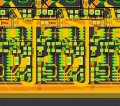
I have attached my schematic, and PCB drawings
I did add two N-Channel MOSFETS to "enable" the circuit because 'batt+' can see up to 60v. **The N-FETs do not overheat.
One of my chargers on my circuit does not contain the N FETs section and it experiences the same overheating problem.
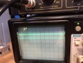
I thought that maybe the gate wasn't getting pulled down enough.
My scope sucks but you can see in the pics that it appears to be working. (volts/div = 5v)
The input is 12v and draws roughly 1.5A.
I am stumped on what is causing the problem because I selected components rated for higher current (13.5 A MOSFET, 5A diode) than used in their demo board.
I am having problems with the P- MOSFET and diodes overheating and eventually desoldering themselves.
I basically followed the schematic from their demo board...
http://cds.linear.com/docs/en/demo-board-manual/dc551A-A.pdf
I have attached my schematic, and PCB drawings
I did add two N-Channel MOSFETS to "enable" the circuit because 'batt+' can see up to 60v. **The N-FETs do not overheat.
One of my chargers on my circuit does not contain the N FETs section and it experiences the same overheating problem.
I thought that maybe the gate wasn't getting pulled down enough.
My scope sucks but you can see in the pics that it appears to be working. (volts/div = 5v)
The input is 12v and draws roughly 1.5A.
I am stumped on what is causing the problem because I selected components rated for higher current (13.5 A MOSFET, 5A diode) than used in their demo board.
Attachments
-
 85.1 KB Views: 32
 -
 374.7 KB Views: 26
 -
 151.8 KB Views: 25
 -
 107.9 KB Views: 28
 -
 100.1 KB Views: 25