 Facebook
 Google
 GitHub
 Linkedin
I am having trouble understanding proper MOSFET gate logic in my design. I need a battery multiplexer. Two separate batteries with the same nominal voltage are expected to power my design - if one goes out the other one kicks in to power up the design. I am hoping to use a dual p-chan mosfet switch to multiplex the batteries.
I need to better understand which pin (source or drain) is the input and which pin is the output. I know both output pins will ultimately be tied together to form the circuit.
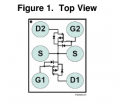
Can someone please help me better understand which pins to connect the batteries to, which pins will be tied together and which pins will output the power. I know I need two mosfet ics to complete the design. The mosfet ic I plan to use in my design is attached. I can draw out some more schematics and info if that would be helpful.
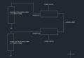
I attached a little drawing that loosely explains what it will look like neglecting the extra pins on the mosfet.
I need to better understand which pin (source or drain) is the input and which pin is the output. I know both output pins will ultimately be tied together to form the circuit.
Can someone please help me better understand which pins to connect the batteries to, which pins will be tied together and which pins will output the power. I know I need two mosfet ics to complete the design. The mosfet ic I plan to use in my design is attached. I can draw out some more schematics and info if that would be helpful.
I attached a little drawing that loosely explains what it will look like neglecting the extra pins on the mosfet.
Attachments
-
 29.7 KB Views: 22
 -
 135.3 KB Views: 23


