battery charger

Thread Starter

majorkuso

Joined Aug 21, 2009
59
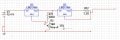
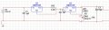
I am trying to build a battery charger using a dc wall transformer that outputs 12.45 volts up to 1.5amps I am trying to scale it down to charge the battery at 7.0 volts and limit the current to .1 amps if possible to extend the life of the batteries also I would like to set it so that maybe a diode will light when it is done charging the batteries are 6.9 volt 4.AH Lithium Polymer batteries if I remember correctly.

I have a large supply of 1/4 watt resistors, diodes about 5 LM317 and a few 7805s ceramic and electrolytic capacitors are no Problem The main Problem I am facing is dissipating heat I would like to build it without a heatsink and fan if possible.

Thanks in advance for your help.
 

wayneh

Joined Sep 9, 2010
18,104
If you are limiting current to 100mA, heat isn't going to be a big problem. You don't need a fan but a heatsink is always a good idea. You're dropping about 6 volts at 0.1A, or 0.6W.

You might look at the LM3914 IC for watching the voltage. It can give you a bargraph-style indication with 10 levels. You can accomplish something similar with a comparator such as the LM393.

But, you should be looking at an IC specifically designed for charging and tending the battery chemistry you have. That'll allow for rapid charging of a discharged battery followed by a safe trickle or whatever profile is best for your battery.
 

Kermit2

Joined Feb 5, 2010
4,162
I would highly recommend you utilize a commercially available charger for use with Lithium Polymer batteries.

They can do SERIOUS harm to you if not properly charged and/or monitored.

Using a commercial charge control IC like the one above is the next best thing.

I never say a word to someone wanting to make a charger for lead acid or NiCd, but Lithium Polymer, it needs to said again, is DANGEROUS if mishandled
 

Thread Starter

majorkuso

Joined Aug 21, 2009
59
Sorry for the confusion the batteries are sealed lead acid I do not have them on hand and thought they were li-po.
 

Kermit2

Joined Feb 5, 2010
4,162
In that case your 12.45 volt 'wall wart' will not be up to the task of charging 12 volt batteries. 6 volt batteries could be accomplished, but the low current from the supply might make that too slow.
 

bountyhunter

Joined Sep 7, 2009
2,512
Sorry for the confusion the batteries are sealed lead acid I do not have them on hand and thought they were li-po.
You could just use the LM317 with a trimpot so you can adjust the open circuit voltage to the precise value the battery maker recommends, probably about 6.8V ballpark.

The LM317 has thermal protection so a heatsink isn't absolutely required, but it's a good idea.

The LM317 will be putting out whatever current is required to force the battery up to the set voltage, maybe as high as about 2A maximum so it might go into thermal shutdown without heatsink. If the battery is good, the voltage should come up quickly and taper off the charge current.
 

Thread Starter

majorkuso

Joined Aug 21, 2009
59
That is what I may do but when i just hook my meter to it the lm317 gets really hot too hot to touch I need to find my heat sinks and put one on it

i limited the current with one lm317 and then taking the second one and putting the voltage at 7 from the current limited lm317 the current is about .14 on the output at 7 volts
 
Last edited:

wayneh

Joined Sep 9, 2010
18,104
...when i just hook my meter to it the lm317 gets really hot too hot to touch...
That ain't right!
Are you trying to measure current output by placing the meter leads in parallel with ground and the output pin? This is essentially shorting the LM317 until it cuts out due to thermal overload. You must measure current in series with some load.
 

Thread Starter

majorkuso

Joined Aug 21, 2009
59
When I put the battery on it drops to 5.54 volts I will look at it later and see if I can find the problem, but would anyone know why
 

Thread Starter

majorkuso

Joined Aug 21, 2009
59
the batteries are rated at 6 volt 4.6ah I can get the voltage to output at 6.9 to 7 but the current is far below the the 100mA. half an amp should suffice nicely, but i was shooting for .1A so as to not charge too quickly. The DC Wall adapter is rated at 12 volts at 1.5A or 1500mA.
 

Attachments

Audioguru

Joined Dec 20, 2007
11,248
You connected the regulators backwards. The current regulator should be first (at the 12V power supply) then the voltage regulator should be connected to its output and to the battery.
The current regulator has a voltage drop of up to 2.75V before it limits the current.

The voltage regulator needs a 0.1uF ceramic input capacitor and a 1uF to 10uF electrolytic output capacitor as shown on the datasheet. The current regulator also needs a 0.1uF ceramic input capacitor also shown on the datasheet.
 

Thread Starter

majorkuso

Joined Aug 21, 2009
59
Well I can't say it has not been educational I adjusted the schem to limit current first then regulate voltage. I don't have any resistors that can handle the current regulator. I may see if I have any one watts and may see about put some in parallel to split the current, I have to go to town this weekend, may stop buy radio shack and see what they got. looks to be 1 to 2 watt resistor is needed.
 

Attachments

Audioguru

Joined Dec 20, 2007
11,248
Use simple arithmatic to calculate the resistor power:
1.25V squared/3.2 ohms= 0.488W. A 1/2W resistor will get extremely hot so use a 1W resistor.

Resistors are bought at a real electronics parts distributor store, not a (RadioShack) cell phone sales store.
 
Top