 Facebook
 Google
 GitHub
 Linkedin
Hey there! It is my first time posting to the forum so please let me know if I'm doing something wrong

So recently I've been interested in designing a circuit that switches from one battery pack to another using one digital pin of my arduino micro (yes, I understand that both power supplies can be added in series but its more of a proof of concept).
Anyways the specs of my batteries are as follows:
Normal battery: 6v @ 2800mah
Backup: 7.2v @2800mah
Peak current draw of the circuit to be powered: somewhere around 850ma to 1amp (w.i.p.)
Voltage regulator: https://www.pololu.com/product/2111 (7amp version)
I have voltage sense circuitry that I read with my microcontroller to tell me when the normal battery drops below 5.5v (my regulator requires atleast 4.5v to output 5v) at which point the normal battery will switch off and the backup will turn on. Obviously this has to be done rather quickly (<50ms?) otherwise we loose power to arduino (bad).
Temporarily I've been using a 5vdc relay, but it requires like a 1000uf tank capacitor on the reg input otherwise the power to the arduino drops out. I suppose as the circuit gets more and more finished towards the full 850ma to 1amp peak current that I mentioned above this value will have to increase. This solution seems rather clunky.
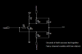
So: I was thinking of using a couple of P-channel FETS and a logic inverter. Such that, when the arduino digital output is LOW to the circuit the FET for the normal battery is open. However, when the output is HIGH the FET for the backup opens and concurrently the FET for the normal battery closes.
I don't want to use diodes, or ideal diode packages such as the LTC4414 or 4415.
I've attached a schematic with some possible part types and layout. I'm not sure if it will work, infact, all I am sure about is that the logic inverter will work.
The schematic can be viewed/edited here (I believe): https://easyeda.com/editor#id=c424c536b26a46c08d017fe005df420f
So recently I've been interested in designing a circuit that switches from one battery pack to another using one digital pin of my arduino micro (yes, I understand that both power supplies can be added in series but its more of a proof of concept).
Anyways the specs of my batteries are as follows:
Normal battery: 6v @ 2800mah
Backup: 7.2v @2800mah
Peak current draw of the circuit to be powered: somewhere around 850ma to 1amp (w.i.p.)
Voltage regulator: https://www.pololu.com/product/2111 (7amp version)
I have voltage sense circuitry that I read with my microcontroller to tell me when the normal battery drops below 5.5v (my regulator requires atleast 4.5v to output 5v) at which point the normal battery will switch off and the backup will turn on. Obviously this has to be done rather quickly (<50ms?) otherwise we loose power to arduino (bad).
Temporarily I've been using a 5vdc relay, but it requires like a 1000uf tank capacitor on the reg input otherwise the power to the arduino drops out. I suppose as the circuit gets more and more finished towards the full 850ma to 1amp peak current that I mentioned above this value will have to increase. This solution seems rather clunky.
So: I was thinking of using a couple of P-channel FETS and a logic inverter. Such that, when the arduino digital output is LOW to the circuit the FET for the normal battery is open. However, when the output is HIGH the FET for the backup opens and concurrently the FET for the normal battery closes.
I don't want to use diodes, or ideal diode packages such as the LTC4414 or 4415.
I've attached a schematic with some possible part types and layout. I'm not sure if it will work, infact, all I am sure about is that the logic inverter will work.
The schematic can be viewed/edited here (I believe): https://easyeda.com/editor#id=c424c536b26a46c08d017fe005df420f
Attachments
-
 13.2 KB Views: 16


