Is this the correct way to wire up a 5v circuit to use battery backup?

Thread Starter

Cancun Manny

Joined Jul 21, 2024
8
So I started to learn how to make my own UPS watching youtube videos, and now that I am looking deeper into it seems many if not most of these videos are wrong. I know very little, almost nothing about electronics, but it seems those that do "know" often criticize those that share YT videos but no one seems to reference a good video source or a good schematic we can look at.

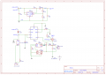
Using different sources I came up with this schematic, would this be considered the "right" way of setting everything up?

Schematic_1BMSBatterySystem_2024-07-21 (1).png

The HLK10M05 is an AC to DC 5v 2A converter
The TP4056 module doesn't include a BMS, it provides cc and cv
The BMS I don't have an actual model number for, it is a 1s 3A BMS
The 18650 battery is unprotected
The SX1308 Step UP Booster would be set to offer 5v after the D2 Schotty Diode
The IRF9540 Power MOSFET prevents load on battery when main power source is present

Is this the correct way to set up a 5v project that includes battery backup?
 

MisterBill2

Joined Jan 23, 2018
27,164
The bad news is that because I would be guessing as to just how a few of those modules work, I would be unable to provide a adequate evaluation of your created design. So based on that, it "looks good" , but no promise. That is an evaluation based on guesses.
 
Your schematic looks pretty solid for a 5V project with battery backup. Just a couple of things to double-check: ensure the TP4056 and BMS are compatible and can safely handle your 18650 battery. Also, make sure the SX1308 step-up booster is properly adjusted for stable output.

Overall, your setup seems right, but always be cautious and double-check connections and component ratings.
 

Thread Starter

Cancun Manny

Joined Jul 21, 2024
8
The bad news is that because I would be guessing as to just how a few of those modules work, I would be unable to provide a adequate evaluation of your created design. So based on that, it "looks good" , but no promise. That is an evaluation based on guesses.
Thank you for the feedback. Yesterday I spent all day reading and watching videos on the subject. I was under the impression that "modules" where standard, but now I understand they are not. For example, the TP4056 module some only have overcharge protection, while others full protection like over discharge, short circuit, etc.

If I am understanding correctly what are "standard" are the actual chips, also called IC's. By following the datasheet I add the additional components and I can create my own TP4056 modules.

In a nut shell today I totally understand what you mean about having to "guess" if my setup would work or not. In theory if I pick the correct modules then yes my schematic would work. By the way I did make a couple of changes.
 

Thread Starter

Cancun Manny

Joined Jul 21, 2024
8
Your schematic looks pretty solid for a 5V project with battery backup. Just a couple of things to double-check: ensure the TP4056 and BMS are compatible and can safely handle your 18650 battery. Also, make sure the SX1308 step-up booster is properly adjusted for stable output.

Overall, your setup seems right, but always be cautious and double-check connections and component ratings.
Thanks for the feedback.

I did make a couple of changes based on a suggestion. I now moved the MOSFET to connect directly to the TP4056 Vout, so when MOSFET is off only current being drawn from the battery would be the diode in the MOSFET.

The other changes I made was to replace schotty diode with reglar 1n4007 diode and to move the SX1308 to boost up which ever power supply that is selected. The main power source starts at 5v, but drops after going through the diode. The battery supply offers 4.2v. By selecting the V source first, then sending it to the SX1308 will give me a steady 5v regardless of which V is selected, and when main power supply goes out battery backup would kick in "quicker" as the boost is already up and running.

I only have one more suggestion I can't seem to figure out mainly because it seems most of the videos I've watched make the same mistake. I am being told that when the MOSFET is off because of the diode it continues to put a very small load on the TP4056, enough to confuse it not to know when the battery is actually full. This "floats" the battery, or the charging of the battery, which is not good for the battery.

I am leaning towards me being ok, since 1) most videos and instructables seem to do it that way without any issues and 2) I have the TP4056 connected to the BMS, so even if TP keeps sending current to the BMS when battery is full, the BMS would prevent the battery from overcharging. (Not sure if that actually takes care of the floating)
 

sghioto

Joined Dec 31, 2017
8,633
Updated Schematic
I question the TP4056, U4. It says a module, what other components are involved, is there a schematic of this module?
Also showing the output of the 5 volt supply shorted, connections reversed and no ground connection on the -IN connection of the TP4056 module.
1721683469313.png
 
Last edited:

Thread Starter

Cancun Manny

Joined Jul 21, 2024
8
I question the TP4056, U4. It says a module, what other components are involved, is there a schematic of this module?
Also showing the output of the 5 volt supply shorted, connections reversed and no ground connection on the -IN connection of the TP4056 module.
View attachment 327591
Still getting the hang of using EasyEDA and sometimes I move things around without even noticing. Thanks for pointing it out.

As far as the TP4056 I finally understand the concept that the TP4056 IC/chip is standard but the TP4056 modules themselves are not. The we add into the mix the "fake" modules being sold on aliexpress claiming they are using certain chips when they are not, yet their devices still perform as expected so many of us continue to use them.

This is what the updated schematic looks like
 

Attachments

MisterBill2

Joined Jan 23, 2018
27,164
It can indeed be rather confusing about device identifications versus product part numbers. Way back in the early Vacuum tube era it became clear that there would be multiple companies choosing to produce devices with very specific, identical, characteristics. Thus an agreement that those devices would carry a specific number if they conformed to a published set of characteristics. This provided a great benefit for both producers and users. That same agreement applied to transistors and then integrated circuits, and allows designing using information from data files applicable to products from many producers. The published characteristics are unique to the product regardless of manufacturer. (At least that is the intention)

No such scheme applies to the proprietary module designs, which carry numbers selected by the producers, but which do not relate to any published standard. So those modules may be whatever the producer chooses to provide, and the only information available is what the producer may claim to be correct.
So for those modules, from amazon and similar suppliers, the only information we can be sure of are the price and the shipping weight. Performance data may be presented on the listing, and might be correct.
 
Top