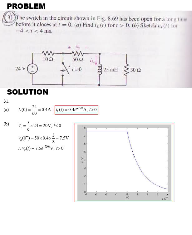
[BASIC RC and RL circuits] -- Find iL(t) when t>0

Thread Starter

killingfield1975

Joined Oct 22, 2009
7


From what I understand when t>0 the switch is closed. When it is closed the inductor goes away... is this correct?

When I solve for iL(0) I get 24/90 instead of 24/60.
I also get iL(t) = 0.26e^3600t

As for part B I am completly lost where did they get V = (5/6) x 24 = 20V from?

Please help guide me thanks!
 

t_n_k

Joined Mar 6, 2009
5,455
As for part B I am completly lost where did they get V = (5/6) x 24 = 20V from?
Looking at the circuit at t<0 the total supply voltage of 24V is supported across the 10Ω and the 50Ω in series. As jstrike21 points out the ideal inductor has no voltage across it at t<0 i.e. just prior to the switch closing.

So using the voltage divider rule prior to the switch closing

Vx(t<0)= {50/(50+10)}x24={50/60}x24={5/6}x24
 

Thread Starter

killingfield1975

Joined Oct 22, 2009
7
At T=0 the inductor will act as a short, therefore you don't add in the 30 ohm resistor because no current will go to it
Thanks JStrilke but I'm not following you. If you short the inductor wouldn't current flow from the 10 ohm to 50 ohm to the 30ohm resistor? By eliminating the 25mH inductor I am left with this...


if the inductor is removed, the 30 ohm resistor stay, correct?
 

t_n_k

Joined Mar 6, 2009
5,455
T
If you short the inductor wouldn't current flow from the 10 ohm to 50 ohm to the 30ohm resistor? By eliminating the 25mH inductor I am left with this...

if the inductor is removed, the 30 ohm resistor stay, correct?
No the circuit is incorrect as you have drawn it.

The inductor eventually (after a "long time") bypasses the 30Ω and current does not flow in the 30Ω until the switch is closed at t=0.

So effectively before t=0 you have the current flowing from the 24V source +ve, through the 10Ω and 50Ω, then directly "shorted" through the inductor and finally returning to the supply -ve. Effectively the supply "sees" only the 10Ω+50Ω in series - with the inductor having zero resistance. The initial inductor current is then 24/(10+50)=24/60 = 0.4A.
 

Thread Starter

killingfield1975

Joined Oct 22, 2009
7
Ok I think I get it. so at t<0 the switch is open. during this time the inductor sucks up all the current so there is no current flowing to the resistor. but at t>0 the switch is closed, current then flows to the 30ohm resistor?

No the circuit is incorrect as you have drawn it.

The inductor eventually (after a "long time") bypasses the 30Ω and current does not flow in the 30Ω until the switch is closed at t=0.

So effectively before t=0 you have the current flowing from the 24V source +ve, through the 10Ω and 50Ω, then directly "shorted" through the inductor and finally returning to the supply -ve. Effectively the supply "sees" only the 10Ω+50Ω in series - with the inductor having zero resistance. The initial inductor current is then 24/(10+50)=24/60 = 0.4A.
 

t_n_k

Joined Mar 6, 2009
5,455
"..the inductor sucks up all the current.." isn't how I'd put it, but I guess that will do if you really have grasped the concept.

However can you explain why after the switch closes current will again flow in the 30Ω?
 

Thread Starter

killingfield1975

Joined Oct 22, 2009
7
Is it because current is flowing in parallel path when it closes? Doesn't current get devided through the branches or something when it flows in parallel?
= ( I'm wrong huh?


"..the inductor sucks up all the current.." isn't how I'd
put it, but I guess that will do if you really have grasped the concept.

However can you explain why after the switch closes current will again flow in the 30Ω?
 

t_n_k

Joined Mar 6, 2009
5,455
Prior to the switch closure the circuit is at steady state with the inductor holding an unchanging current value of 0.4A.

Before t=0 the inductor has zero voltage across it. Why? Firstly, because the current is not changing (no L.di/dt effect) and secondly, because it has zero DC resistance.

Once the switch closes, the inductor current 0.4A can no longer be maintained, since the switch completely bypasses the source current to that part of the circuit which is in parallel with and to the right of the switch. The inductor current will then tend to decrease towards zero as time progresses. Simultaneously, the inductor voltage will rise as the generated back emf [L.di/dt] tends to oppose this change in current. The inductor voltage (or back emf) will be of a certain magnitude and polarity so as to maintain a current of 0.4A at the instant t=0. For this to be the case, the lower side of the inductor will be more positive with respect to the top side.

Since both the 50Ω & 30Ω resistors are effectively in parallel with the inductor from t=0 onwards, they will share the inductor current in proportion to their respective values. At t=0, the 50Ω will take 3/8 ths of the current (.15A) and the 30Ω will take 5/8 ths of the current (0.25A).

The voltage drop across each resistor (and inductor) must be the same. The magnitude of voltage at t=0 will be 7.5V and it will have the same polarity as that indicated for the variable Vx shown on the circuit.
 
Top