Basic preamp for mic and line-in input

Thread Starter

satcom

Joined Apr 1, 2015
65
I have small project for home, LED color organ, which controls LED light depending on frequency of the input audio signal (either from electret mic or line-in). Input audio sources are selected by switch. The LED strips 5050 (up to 600 LED each) on the output connected to Mosfets. Power supply is +12V. The device is basic enough, I need help regarding pre-amp for electret mic and line-in, I need something just is just suitable for the purpose.
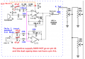
I have sample preamp design based on LM324 and +9V supply, but this IC definitely isn't good for pre-amp.

upload_2018-4-18_15-0-36.png

Can anyone suggest better pre-amp design for this purpose? (a schematic diagram will be useful).
 

Attachments

Last edited:

Audioguru

Joined Dec 20, 2007
11,248
An LM324 is horrible for an audio preamp because it is noisy, has crossover distortion and has trouble with high level frequencies above only 2kHz. But a color organ does not care.

The schematic has the electret mic powered directly from the battery which might cause low frequency oscillation. It should be fed from another RC filter.

The opamp for the line input is a stereo to mono mixer that is not needed if the line input is a single mono input.
An LM358 has the same opamps as an LM324 but only two of them and is in an 8 pins package.
 

Thread Starter

satcom

Joined Apr 1, 2015
65
Yes I know that LM324 is not suitable for preamp. So I want to replace it with something more suitable. But LM358 and LM324 are part of the same family, so there is no much difference.
 

Audioguru

Joined Dec 20, 2007
11,248
Yes I know that LM324 is not suitable for preamp. So I want to replace it with something more suitable. But LM358 and LM324 are part of the same family, so there is no much difference.
Why replace it? You do not have an audio preamp, you have a color organ that does not "hear" the audio problems.
 

Thread Starter

satcom

Joined Apr 1, 2015
65
well, preamp is still audio part in this device, and there is waste amount of another op-amp that will be more suitable.
 

Audioguru

Joined Dec 20, 2007
11,248
If this preamp drives a color organ and an audio amplifier driving a speaker then you will probably have acoustical feedback howling. Maybe you want to record the audio then using an audio opamp is best. There are hundreds of newer and better audio opamps available. Most are available as a single, a dual and a quad.
 

Thread Starter

satcom

Joined Apr 1, 2015
65
I want try TL072 dual opamp. Can someone post preamp circuit diagram for electret mic and line-in inputs? (+12V single supply)
 

Audioguru

Joined Dec 20, 2007
11,248
I want try TL072 dual opamp. Can someone post preamp circuit diagram for electret mic and line-in inputs? (+12V single supply)
Exactly the same circuit that you showed except change R1 to 10k but disconnect it from +12V. Add a 1k resistor to +12V and connect it in series with R1. Where the two resistors join add a 47uF capacitor to ground. The added resistor and capacitor filter the current to the mic to avoid hum and oscillation. The TL072 has fairly low noise, very low distortion and works well to 100kHz.

Since the mic opamp is inverting it has a low input impedance then C1 must have a high value (it is too high at 4.7uF) then it must be an electrolytic that is usually polarized. But you don't know its polarity. Replace C1 with a 0.47uF film type capacitor.
 

Thread Starter

satcom

Joined Apr 1, 2015
65
Since the mic opamp is inverting it has a low input impedance then C1 must have a high value (it is too high at 4.7uF) then it must be an electrolytic that is usually polarized. But you don't know its polarity.
did you mean it's difficult to determine the polarity of electrolytic capacitor?
 

Audioguru

Joined Dec 20, 2007
11,248
did you mean it's difficult to determine the polarity of electrolytic capacitor?
Which way should C1 be connected? The mic end might be more positive than the opamp or the opamp might be more positive than the mic.
Polarity does not matter with a film capacitor.
 

Thread Starter

satcom

Joined Apr 1, 2015
65
shema1.png

so you mean changes as above. I don't know how to modify line-in channel of TL072, need to choose proper values for passive R, C elements.
I want that device can work from line out signal from most audio sources, afaik the output voltage of the source device varies widely, 0.3--2V
I need that signal was not clipped.
 

Audioguru

Joined Dec 20, 2007
11,248
You adjust the volume control to avoid clipping. You do not say how much input level the LED circuit needs so the gain of 1 for the line input might be too low.
You made a few errors, here are my corrections:
 

Attachments

Thread Starter

satcom

Joined Apr 1, 2015
65
I don't know about minimum input required, I modified the existing circuit which does not use pre-amp at all: instead, it uses small audio transformer for signal boost (MODE #60-282-0) The original circuit works from a headphone output (quite low power) and also from any power amplifiers output. So preamp need be as buffer amplifier that should cover that range.
Would be better use an inverting amplifier, just as a typical application for an operational amplifier?
TL072 datasheet.
 

Audioguru

Joined Dec 20, 2007
11,248
An inverting opamp has a fairly low input impedance. A non-inverting opamp can have an extremely high input impedance.
You have a stereo to mono mixer. An inverting opamp is usually used as a mixer.
 

Audioguru

Joined Dec 20, 2007
11,248
If you need a buffer to drive the low resistance of the 5k volume control then you should use a 20k ohms or 50k ohms volume control that does not need to be driven with a buffer.
 
Top