 Facebook
 Google
 GitHub
 Linkedin
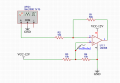
I would appreciate it if someone could give me some guidance. I appreciate that the below circuit is simple and doesn't contain some of the capacitors but I tried adding those as well and it seems to make no difference with what I am experiencing. When I attach a scope to the output, pin 1 of this LM358 OpAmp, the signal is a straight line clamped against the top rail.
However, I do get the amplified Sine Wave when I change resistors R3 and R4 so the voltage at volProve1 = 1V (and not 6 Volts) and I don't understand why that is. I thought the R3/R4 voltage divider raises the virtual ground by 6 Volts so the amplified signal is offset against that 6V virtual ground but that doesn't seem to happen. Apologies if this is a very basic question.

However, I do get the amplified Sine Wave when I change resistors R3 and R4 so the voltage at volProve1 = 1V (and not 6 Volts) and I don't understand why that is. I thought the R3/R4 voltage divider raises the virtual ground by 6 Volts so the amplified signal is offset against that 6V virtual ground but that doesn't seem to happen. Apologies if this is a very basic question.
Attachments
-
 80.4 KB Views: 3


