 Facebook
 Google
 GitHub
 Linkedin
Hello all,
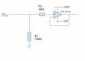
I have a simple impedance calculation question regarding the circuit below,

The circuit consists of a simple buffer circuit with a LM741 Op-Amp, the purpose of the resistors is to increase the overall circuit impedance (and other applications not related to this question). Also from the LM741 datasheet, the input resistance of this op-amp is typically 2MΩ.
I have replicated this particular part of the circuit in a lab and when I use my multimeter to measure impedance (from input to ground), the impedance measures around 4.2 MΩ.
How does the impedance calculate to this value?
What will the impedance read when I replace the LM741 op-amp with a OPA1662AIDRQ1 op-amp?
The differential resistance of the OPA1662AIDRQ1 op-amp is 170KΩ, the common mode resistance is 600KΩ .
I have a simple impedance calculation question regarding the circuit below,
The circuit consists of a simple buffer circuit with a LM741 Op-Amp, the purpose of the resistors is to increase the overall circuit impedance (and other applications not related to this question). Also from the LM741 datasheet, the input resistance of this op-amp is typically 2MΩ.
I have replicated this particular part of the circuit in a lab and when I use my multimeter to measure impedance (from input to ground), the impedance measures around 4.2 MΩ.
How does the impedance calculate to this value?
What will the impedance read when I replace the LM741 op-amp with a OPA1662AIDRQ1 op-amp?
The differential resistance of the OPA1662AIDRQ1 op-amp is 170KΩ, the common mode resistance is 600KΩ .
Attachments
-
 29.9 KB Views: 2


