Base resistor and MOSFET + Rectifier Diode Selection for Solenoid actuation?

Thread Starter

protoengineer

Joined Oct 7, 2018
9
Hi all,

Problem:
I have to calculate the base resistance required between a voltage supply and the base leg of a MOSFET transistor, given the following parameters:

1) voltage supply to the base leg is 5V and the emitter leg is connected to ground with the voltage supply.
2) the collector leg is connected to a rectifier diode and solenoid (inductor) which are in parallel with each other.
3) the solenoid and diode are connected to a separate 12V voltage supply which is connected to ground with the emitter leg and base voltage supply.
4) the solenoid operates at 24W with an equivalent 6ohm resistance.

I also have to figure out what transistor and what diode I can use for the system.

My attempt:
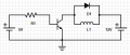
I made this SPICE model:


So, I assumed that you could use KVL on the left side of the circuit, with Ohm's Law V=R*i -> 5=R1*i1.
I also assumed that using the equivalent resistance of the solenoid, the current across it can be calculated with P=V*i -> 24=12*i -> i_L1=2A.
So, using KCL, I know that if I choose a diode with a 1A rating, the current into the parallel connection should be 2A+1A=3A.
If I then choose a MOSFET transistor with a gain of 1000, the current out of the resistor should be i1=3mA.
Thus, using Ohm's Law again, with V=R*i -> 5=R1*0.003 -> R1=1667 Ohm.
I know that a 1N4004 has a 1A rating and a TIP120 has a 1000 gain, so if the system uses two standard resistors in series in place of R1 with resistances of 1600 Ohm and 68 Ohm, with a 1N4004 and a TIP120, the solenoid should operate at 23.97W and 12V. The power on the resistors is less that 15 mW combined so a 250 mW rating on the resistors would not be overloaded.

Can someone please tell me if I did this correctly? Thank you very much.
 

Attachments

dl324

Joined Mar 30, 2015
16,846
When operating TIP120 as a switch, you use a beta of 250:
upload_2018-10-7_19-14-15.png
upload_2018-10-7_19-14-37.png

Solenoid current is 2A, but you can probably use 1N4001:
upload_2018-10-7_19-16-36.png
upload_2018-10-7_19-16-56.png
 

Thread Starter

protoengineer

Joined Oct 7, 2018
9
Hi,

Can you explain why the 1N4001 should work? Is the diode needed more for protecting against the full 2 A used by the solenoid at shutoff or the large voltage produced at that time? As in, is it more important to block up to 50 V or 2 A?

Thanks.
 

dl324

Joined Mar 30, 2015
16,846
Can you explain why the 1N4001 should work? Is the diode needed more for protecting against the full 2 A used by the solenoid at shutoff or the large voltage produced at that time? As in, is it more important to block up to 50 V or 2 A?
The 50V reverse breakdown voltage is more than sufficient for your 24V supply.

When the solenoid is switched off, the rectifier diode will need to tolerate 2A while the field collapses. Since the diode tolerates a 30A surge current for 8.3ms, I'd try it if this isn't for a commercial product.

For a more robust design, use a 3A rectifier.
 

ebp

Joined Feb 8, 2018
2,332
When you calculate the resistor for the base you need to subtract the forward voltage of the base-emitter junction from the applied voltage to get the voltage across the resistor, though if the input voltage is high enough you can ignore this. The bipolar junction transistor ("BJT" or "bipolar transistor" or just "transistor") you are using is a "Darlington pair" or "Darlington transistor", which uses two transistors to get much higher current gain than you can get from a single power BJT. This means that there are actually two "base-emitter" voltage drops in series. When current is flowing into the base, the voltage of the base will be about 1.2 to 1.4 V positive with respect to the emitter for an NPN Darlington. So, the voltage across the resistor is therefore (5 - 1.4) volts and you would calculate the resistor accordingly, making it 1200 ohms for 3 mA. If the thing supplying 5 V is a logic output, it would be prudent to look at the data for actual output voltage versus current, and even consider that the supply voltage might be a bit less than 5 V.

Determining the value you should actually use is a bit messy. The datasheet says the minimum gain is 1000 at a particular set of conditions, and you need to review the conditions to see if they are reasonably applicable to your circuit. To do this, you need to have a look at the curves for current gain. Because you are using the transistor as a switch, you typically would want it to "saturate." Ignoring the details for now, this means that you get it to turn on with something near the lowest collector-emitter voltage you can accomplish - not necessarily the absolute lowest, but something fairly close.

https://www.onsemi.com/pub/Collateral/TIP120-D.PDF
If you look at the ON Semi datasheet (I often prefer ON's datasheets to others, even though this was originally a TI part), you see that that gain is specified at half an amp and at 3 A, and at 25 °C. Figure 9 of the datasheet is helpful. It shows typical gain over a range of collector currents at different temperatures. It is generally bad design to rely on typical values, but considering them is instructive if there is enough detail provided. The typical gain at 2 A at 25 °C is over 4000. Even at -55 °C it is over 2000. Figure 10 is also helpful and actually has a curve for 2 A at 25 °C. At a base current of 0.5 mA it is just getting into saturation. At 1 mA it is well into saturation, though not at the lowest possible collector-emitter voltage. There is nothing to be gained by trying to reduce the collector-emitter voltage by a further 30 or 40 millivolts. If I were using this transistor (and I have in an industrial control product), I would consider the fact that the gain is down by a factor of about 2 at -55 °C so I'd take 2 mA as a reasonable target for base current for 2 A of collector current. That just happens to correspond to a gain of 1000. I'd feel quite comfortable with using that 1000 gain figure. With 3.6 V across the base resistor, 1800 ohms would yield 2 mA. If should be obvious that approximations are at play throughout this evaluation, so there would be no need to use some precise value. 1.8k happens to be a standard value. If I had a circuit board that only had one 1.8k resistor on it but had some 1.5k elsewhere, I'd use 1.5k for the base resistor and have a little extra margin. I might use 2k if I were using that value somewhere else on the board. If I didn't have to operate at low temperature, I'd be totally OK with 2.2k, which is a very commonly used value. I'd also go down to 1k without concern as long as whatever was supplying the 5 V could deliver the small additional current.

Now, returning to the original circuit. No current flows in the diode when the transistor is on, other than a "leakage" current of a few microamps, so it can be ignored. The transistor only has to switch the 2 A for the solenoid. When the transistor turns off, the diode will conduct. The solenoid is an inductor which will try to keep the current constant, both in magnitude and direction. The 2 A current that flowed through the transistor would flow through the diode, decreasing over time to zero as the energy stored in the inductor was discharged (the energy goes into heat in the diode and the resistance of the solenoid winding). A 1 ampere diode will easily handle 2 A as a repetitive transient. if I were switching the solenoid at high frequency, I might consider a higher diode rating based on average power. It is very unlikely that you could make the solenoid operate mechanically at a frequency anywhere near high enough to warrant a higher current diode. Using a "freewheeling" diode like this actually increases the time it takes for the solenoid to release. In some cases that might be an issue and a method that provided a path for the current but allowed a higher voltage would be better.
 

Thread Starter

protoengineer

Joined Oct 7, 2018
9
Think again. Is the voltage across the resistor 5V?
First of all, I just wanted to say thank you dl324 for your continued assistance and thank you ebp for that very thorough response. I was asking for help on other website forums like ElectronicsPoint.com but they have not been nearly as helpful, but have instead been keen to point out my mistakes regardless without offering much insight. I am new to all of this and am trying my darnedest to understand.

I feel like I am missing something very fundamental here. The more I research this circuit, the more confused I get. I have come across different variations: some variations use MOSFETs, others use Darlingtons; some use one diode across the motor, others use one across the transistor, and others use a diode across both; some use just a base resistor, some use just a “pull down” resistor, and still some use both. That gives me 18 different possible configurations.

I. Darlington:

To continue, I believe, based off of ebp’s solution process, I should take into account the “forward voltage” of the NPN transistor system of the Darlington pair. In Fig. 1 below, the left subsystems represent 3 different configurations of the base/pull-down resistors with Q1 as the BJT. Using L1D: taking V1 to be 5V and the load current on the right-side system (i2) to be 2A, and assuming the gain of the Darlington is 1000 with a forward voltage (VF) of 1.4V, then via KVL, the voltage across R1 (VR1) is VR1 = V1 - VF = 5 - 1.4 = 3.6V. Since the desired current across the collector-emitter interface is 2A and the gain is 1000, the current into the base needs to be 2mA. Then, using Ohm’s Law, R1 = VR1/2mA = 1800Ω. Thus, if I am using a Darlington for my transistor in the system, I must use an 1800Ω base resistor to achieve the necessary 2A load current through the solenoid.

Solution: R1 = 1800Ω with Q1 as a Darlington, if using subsystem L1D in Fig. 1.

If subsystems L2D or L3D are better suited for my application of the circuit, then please let me know. I am sort of clueless on how to calculate the current into the base in either of those subsystems, however.

I will address the right-side subsystems in a separate section, since they are essentially equivalent for my questions, regardless of if a Darlington or MOSFET is being used (I think).


Fig. 1 - Darlington possibilities.

II. MOSFET:

Correct me if I am wrong, but I believe the current into the gate of the MOSFET is nearly irrelevant to its operation, and that the voltage across the gate-source interface is what actually matters. Thus, I don’t really need to calculate the current going into the gate, but I should use at least a 1000Ω resistor in subsystem L1M (see Fig. 2) in order to somehow protect the voltage source (e.g. a microcontroller’s 5V signal output pin) and to minimize oscillations. If you could enlighten me on how the 1000Ω value is arrived at, I would appreciate it.

Since the voltage across the gate-source interface is what matters, it is the important value to calculate. I was assuming that if the voltage source (V1) is 5V, then the voltage across Q1 (the MOSFET, in this case) is 5V and is thus well above a “logic level” threshold value (let's say 2V) to turn on the MOSFET and achieve a fully open condition. However, I am not sure if this is accurate when a resistor (R1) as in L1M is included. I think, but am not sure, that if subsystem L3M is instead used, then the voltage will indeed by 5V across Q1 since it will be in parallel with the pull-down resistor (R2) and V1. However, L3M does not use a gate resistor... And I am clueless about L2M.

Questions: Is the gate resistor necessary? Is the pull-down resistor necessary? Should I use both? How would I know the voltage across Q1 if I used both or even just a gate resistor, as in L2M and L1M, respectively, and is my assumption about L3M even true?


Fig. 2 – MOSFET possibilities.

III. Diode Placement:

Referring to Fig. 1 and Fig. 2: is it better to place the diode across the solenoid (R1D/R1M), across the transistor (R3D/R3M), or both (R2D/R2M)? And since the load current is 2A, is it ok to use 1A rated diodes if the solenoid is only activated one time? How does using both diodes affect the necessary rating (if, in a single diode system, a 2A diode is a better idea, then if I switched to a 2 diode system, as in R3M, would two 1A diodes be equivalent for protecting the transistor)?

BIG QUESTION: Which system combination is best? I was originally considering an L1D-R1D or an L1M-R1M system, but I have specifically seen online an L2D-R1D and an L3M-R3M system.


THANK YOU!!!
 

dl324

Joined Mar 30, 2015
16,846
I was asking for help on other website forums like ElectronicsPoint.com but they have not been nearly as helpful, but have instead been keen to point out my mistakes regardless without offering much insight. I am new to all of this and am trying my darnedest to understand.
Give this site some time and the snarky comments will come. With homework, we're constrained in the answers that we give because feeding students answers to homework doesn't help them in the long run. The objective in this part of AAC is to teach, not do.

How many BE junctions are there in a darlington? How much voltage to they drop? In your calculation, you were assuming 0V and that's not correct.
Questions: Is the gate resistor necessary?
Sometimes.
Is the pull-down resistor necessary?
Sometimes. If the gate is always driven, you don't need one.
Should I use both?
It depends on what's driving the gate.
How would I know the voltage across Q1 if I used both or even just a gate resistor, as in L2M and L1M, respectively, and is my assumption about L3M even true?
R2 is to keep the gate from floating and is typically 10k or larger.
Referring to Fig. 1 and Fig. 2: is it better to place the diode across the solenoid (R1D/R1M), across the transistor (R3D/R3M), or both (R2D/R2M)? And since the load current is 2A, is it ok to use 1A rated diodes if the solenoid is only activated one time? How does using both diodes affect the necessary rating (if, in a single diode system, a 2A diode is a better idea, then if I switched to a 2 diode system, as in R3M, would two 1A diodes be equivalent for protecting the transistor)?
TLDR. Diodes across the inductor are more typical because it works for bipolar or MOS transistors. Almost all MOS transistors have an integral diode because it's part of the manufacturing process. Actually, there are two, but one is shorted internally.

Some MOSFETs have the internal diode rated for avalanche discharge, some aren't. In cases where the internal diode is questionable for snubbing, put the diode across the inductor.

BIG QUESTION: Which system combination is best? I was originally considering an L1D-R1D or an L1M-R1M system, but I have specifically seen online an L2D-R1D and an L3M-R3M system.
TLDR. Not everything you see on the internet is trustworthy.
 

MaxHeadRoom

Joined Jul 18, 2013
28,619
Can you explain why the 1N4001 should work? Is the diode needed more for protecting against the full 2 A used by the solenoid at shutoff or the large voltage produced at that time? As in, is it more important to block up to 50 V or 2 A?
Thanks.
Use 1n4007 and it covers practically all eventualities.;)
Max.
 

Thread Starter

protoengineer

Joined Oct 7, 2018
9
It depends on what's driving the gate.
So I know that I can just use a 3A diode like a 1N5400 to be safe since the current is 2A = 24W/12V, and just across the solenoid, and I know that I can use a Darlington TIP120 with an 1800 Ohm base resistor. So my original homework problem is finished. The 1800 Ohm was arrived at by noting the series voltage drop across the two internal transistors, totaling 1.4V, giving the voltage across the resistor as 3.6V, and noting that the gain was 1000, so the base current is 2mA, thus via Ohm’s Law 1800 Ohm = 3.6V/0.002A. I was originally confused about the difference between a Darlington, normal BJT, and MOSFET, but I am clear on that now.

I am interested in implementing this circuit now after reading so much about it. I was reading that if I buy a cheap Arduino Uno, I can hook it up to a breadboard as the 5V voltage supply and use it to open and close the transistor to drive a solenoid powered by a separate power source. I was wondering if I could discuss this with you guys in this thread, since it is going beyond the scope of the original homework problem, or if I should make a new thread in a non-homework section?
 

ebp

Joined Feb 8, 2018
2,332
On the topic of which is better ...

I used to use Darlington transistors for moderate current loads like big contactors (relays). If I were doing it now, I'd probably use a MOSFET, particularly for a surface mount design. The FET might be a bit more expensive than a Darlington, but it could handle more current without any sort of heatsink, if properly chosen, which can save enough money to allow the FET to cost a good deal more more than the BJT and still come out ahead. The 'trick" is to choose the FET based on ON resistance, which is something very important to learn about.

Here's an experiment to do with a simulator or an actual circuit:
Connect a MOSFET to a power source and a load - a resistor for the load will do. Connect the gate through a switch to 8 volts or so (5 is lots for "logic level" FETs, but not all types). Close the switch, then open it and watch what happens to the current through the load. Repeat the experiment with a resistor connected between the gate and the source of the FET. Explain what is happening. Think about the state of an output of a microcontroller when RESET for the controller is asserted (datasheet will explain) and how that would relate to this issue.

In designing electronic systems, you always have to think about the "what happens if ..." scenarios. If a FET briefly turns on a LED when it "shouldn't" it probably isn't a big deal. If it turns on a motor when it shouldn't, it might kill someone.
 

ebp

Joined Feb 8, 2018
2,332
I'd go with starting a new thread.

Experimentation, along with thinking carefully about what is going on, is a great way to learn lots about electronics. You start to develop a "feel" for things, and it can be fun. I think products like the Ardunio are great for experimentation because you can do interesting things without spending a lot of money or a lot of time building everything from scratch. But it is important to put in that time for analysis and understanding if you want to be able to do actual design work.
 

Thread Starter

protoengineer

Joined Oct 7, 2018
9
I'd go with starting a new thread.

Experimentation, along with thinking carefully about what is going on, is a great way to learn lots about electronics. You start to develop a "feel" for things, and it can be fun. I think products like the Ardunio are great for experimentation because you can do interesting things without spending a lot of money or a lot of time building everything from scratch. But it is important to put in that time for analysis and understanding if you want to be able to do actual design work.
Thank you! I like the experiment idea. I will start a new thread outside of the homework section.
 

dl324

Joined Mar 30, 2015
16,846
The 1800 Ohm was arrived at by noting the series voltage drop across the two internal transistors, totaling 1.4V, giving the voltage across the resistor as 3.6V, and noting that the gain was 1000, so the base current is 2mA, thus via Ohm’s Law 1800 Ohm = 3.6V/0.002A.
It you look closely at the information I posted in post #4, the manufacturer is using a beta of 250 when saturation mode operation is desired. We always use a conservative number to guarantee that the transistor will be saturated. For NPN transistors with betas of 200-300, we still use 10 when using them as switches.

If you're operating in the active region, beta depends on Ic, so the manufacturer will typically give you beta numbers for several currents.

You can see the variation of beta with Ic and temperature.
upload_2018-10-8_16-58-59.png
upload_2018-10-8_16-59-26.png
EDIT: IV curves for a PMBT3906, note how beta drops at low Vce
upload_2018-10-8_17-14-35.png
upload_2018-10-8_17-14-49.png
 
Last edited:
Top