Is a base resistor required?

Thread Starter

FuneralHomeJanitor

Joined Oct 12, 2019
64
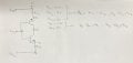
Hey everyone, I am working on a split rail power supply using two resistors as a voltage divider with half the voltage input to a OPAMP voltage followeras a buffer, and I would like to increase the output current by using the pair of bjts in my drawing. If I understand correctly, according to an old textbook, emitter bias allows for me to set the emitter current simply using the emitter resistor, independent of the dc current gain. The emitter voltage appears to be the junction voltage subtracted from base voltage, and in the book, the base voltage for emitter bias circuits is given as simply a DC source, with no base resistor or attention given to the base current. Is this a realistic way to design this circuit? I have not decided how much current I would like yet from the outputs, but the input current from the OPAMP should only be about 20 mA(10 mA for each rail) based on the datasheet.


Why do some examples of emitter bias use a base resistor and base current, while others simply use the base supply as a DC source, and which would be better for my situation?

Would connecting the source directly to the base like that damage the component, or is the base current then limited by the emitter resistor as well?

I am trying to create this so I can play around with other circuits that require a split power supply, it is not too critical to me, I want to keep it simple but make sure I am doing it right, maybe in the end have a source that can give me +-4.5 V with 100 mA max from each rail
 

Attachments

BobTPH

Joined Jun 5, 2013
11,463
Generally, no base resistor is needed when used as an emitter follower. A base resistor is needed used in common emitter configuration.

Your circuit uses both transistors as emitter folliwers, so no base resistor.

Think about how much current flows in the base in each configuration with no resistor and you will understand why.
 

dl324

Joined Mar 30, 2015
18,216
according to an old textbook
Circuit in question:
1720618422996.png
Is that circuit really from a textbook? The transistors are swapped (and you're using a non-standard symbol).
Why do some examples of emitter bias use a base resistor and base current, while others simply use the base supply as a DC source, and which would be better for my situation?
A resistor on the bases would prevent oscillation.
Would connecting the source directly to the base like that damage the component, or is the base current then limited by the emitter resistor as well?
You can omit the resistor. I, and others, often omit resistors on the base. If the circuit oscillates, use the base resistor.

You can use resistors on the emitters collectors if you want to limit current.
EDIT: was referencing your incorrect schematic...
 
Last edited:

Ramussons

Joined May 3, 2013
1,567
Generally, no base resistor is needed when used as an emitter follower. A base resistor is needed used in common emitter configuration.

Your circuit uses both transistors as emitter folliwers, so no base resistor.

Think about how much current flows in the base in each configuration with no resistor and you will understand why.
That circuit is configured as a Class A Common Emitter and the Transistors have no control over the Current which is limited only by the Emitter Resistors.
If the transistors are interchanged, one gets a Class B Common Emitter config.
 

BobTPH

Joined Jun 5, 2013
11,463
That circuit is configured as a Class A Common Emitter and the Transistors
My bad. I just glanced at it and assumed he was using the standard circuit, which is emitter followers. The emitter follower circuit is superior as a current amplifier. You don’t need (or want) voltage gain.
 

Thread Starter

FuneralHomeJanitor

Joined Oct 12, 2019
64
Circuit in question:
View attachment 326669
Is that circuit really from a textbook? The transistors are swapped (and you're using a non-standard symbol).
A resistor on the bases would prevent oscillation.
You can omit the resistor. I, and others, often omit resistors on the base. If the circuit oscillates, use the base resistor.

You can use resistors on the emitters collectors if you want to limit current.
EDIT: was referencing your incorrect schematic...
The circuit itself isn’t from a textbook, but I was using what my book calls emitter bias, where the emitter resistor is used to set the emitter current with the base voltage as a battery connected to it, which is approximately the collector current(for a single BJT circuit), and I was under the impression this would be able to be used in parallel with the two loads so each load would have the same split voltage across it and then I could draw them as current sources and use a current divider for the loads I choose, I would also imagine that some capacitors are probably necessary in the actual use of the circuit
 

dl324

Joined Mar 30, 2015
18,216
I was using what my book calls emitter bias, where the emitter resistor is used to set the emitter current
You should be letting the load(s) determine current in the transistors.

EDIT: Since your intention (from your other post), is to create a vcc/2 reference, you should connect the emitters to the inverting terminal on the opamp.
 

Thread Starter

FuneralHomeJanitor

Joined Oct 12, 2019
64
Thank you to everyone for the help. I applied a little bit of what each person said, simulated the circuit and was pleased with the results, and happy to have a good grasp on the emitter follower which I plan on using much more in the future
 
Top