Bandpass filter challenge

Thread Starter

Zeeus

Joined Apr 17, 2019
616
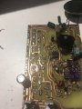
Not sure circuit is relevant to question but....

Designed for about 3.4 Mhz
Inductors (t50-2) and the capacitors are 150pf in parallel with trimmer caps (china)

the problem now is that it peaks at this frequency but it also peaks at about 11Mhz

10Vpp in then a peak at about 3.4Mhz but with amplitude of 1vpp

10Vpp but the peak at 11Mhz almost 9v

Please what can TS do? what is he missing??? Need to solve this badly

Thank you
This is my 2nd attempt. 1st attempt, I used 4.3uH inductors with appropriate caps but same problem
 

Attachments

Thread Starter

Zeeus

Joined Apr 17, 2019
616
Problem was with the board (made pcb by etching)

I made the BPF on a smaller board and it works

Transferring to my main board to test again and look for problem.

Please look at image
Will the traces add unnecessary capacitance to disturb filter? The filter was at the top left

How could I have made the board better?

Please someone, respond.
Thanks thanks
 

Attachments

sparky 1

Joined Nov 3, 2018
756
I will give you an estimate for fun project. It would be better to find the values for 50 -55 Ohm reactance.
An example estimate values given below for building a small custom toroid inductor for shortwave receiving.
https://toroids.info/T50-2.php
3.4 Mhz, 2.82uH, 776pF, 60.3 OhmZ, 24T

The receiver will also be good at receiving the harmonics 6.8, 10.2, 13.6, 17 Mhz
some might use 1.7 as the primary frequency.
http://www.csgnetwork.com/harmonicscalc.html
 
Last edited:

Thread Starter

Zeeus

Joined Apr 17, 2019
616
I will give you an estimate for fun project. It would be better to find the values for 50 -55 Ohm reactance.
An example estimate values given below for building a small custom toroid inductor for shortwave receiving.
https://toroids.info/T50-2.php
3.4 Mhz, 2.82uH, 776pF, 60.3 OhmZ, 24T

The receiver will also be good at receiving the harmonics 6.8, 10.2, 13.6, 17 Mhz
some might use 1.7 as the primary frequency.
http://www.csgnetwork.com/harmonicscalc.html
Understand now your first statement.. Read a book about using 50-150 ohms reactances...Although I used about 190 ohms (my 2nd try)
please why you say 50-55 ohms?

2nd statement, why so? dont understand

Thanks
 
Last edited:

SamR

Joined Mar 19, 2019
5,031
Don't understand what you mean
Homebrew Balun... To match the Balanced Coax w/ the Unbalanced Antenna. All the Balun is, is a filter using a coil on a toroid to match the resonate Freq. of the antenna. Along with the needed resistors and caps.
 

sparky 1

Joined Nov 3, 2018
756
Sorry about cut and paste link. tells when to use 75Ohm. 75 also saves cost on coax using tv cable. So 60 ohm you may not notice any difference but it is standard with most websites you read will agree with your part selection. so it is an excellent question.
https://www.microwaves101.com/encyclopedias/why-fifty-ohms

The 2N5486 preamp when done right is excellent. I have not tryed this circuit. However it appears to be professional. it can't be to far off.
If you try for 35 dB gain on shortwave matched to a 50 ohm with your T50-2 mixer tank it should be very amazing reception.
http://lz1aq.signacor.com/docs/RF_preamplifier_HP_en/RF_preamplifier.htm

This is a test setup that I developed for 9V. if you start off low distortion like this then you can minimize that
and we are talking about wanting to build a preamp so you can grow this into something nice or you can use a coat hanger.
Whatever makes you happy.
2N5486.JPG
 
Last edited:
Top