Band-pass active 4th order filter with cutoff frequencies 400 kHz and 500 kHz

Thread Starter

ksnclaksnc

Joined Jan 30, 2024
39
Hi,

Wow, that's a lot of op amps and a lot of capacitors.
If you really want to try it that way that might work, but usually if you use two capacitors you can get a 2nd order response, and if you use four caps then you can get a 4th order response, with the right circuit that is.
There is a chance what you have there is an 8th order bandpass, but just a chance.

Do you want to go with this topology or look for a simpler solution that uses just two op amps and four capacitors?

Oh BTW, are you going for a cutoff frequency of around 500Hz for the low pass sections?
Note that your capacitors 0.47uf are much larger than you had before when I think you were going for 500kHz.
I have to have a cutoff frequency of 500 kHz
 

Thread Starter

ksnclaksnc

Joined Jan 30, 2024
39
Hi,
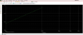
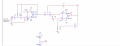
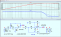
this is the topology that I made by cascading 2 second order filters the first is a high-pass filter and the second is a lowpass. The simulation is working but the response is of an high-pass filterScreenshot (185).pngScreenshot (184).png I do not know what resistors and capacitors to use.
Screenshot (184).png
 

ericgibbs

Joined Jan 29, 2010
21,627
Hi k,
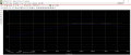
Your plot shows a frequency sweep of 100Hz through 900Hz, but you say you want a filter at 400 kHz and 500 kHz

Try a 100Hz through 1MegaHz frequency sweep for testing.
E
 

LvW

Joined Jun 13, 2013
2,038
I will try cascading a 2nd order lpf filter with a 2nd order hpf, but the teacher did not say how much the resistors are so I don't know how to calculate them. Can someone explain to me, I calculated the central frequency to 100 kHz?
OK - in principle, there are two options:
* Use a suitable program for designing the required filter circuit, or
* do the design by yourself.

In both cases, you must specify the following parameters:
* Order of the filter
* Type of the filter response (Butterworth, Bessel,...)
* Gain at center frequency (if there are any requirements)
* Lower and upper cutoff frequencies (or center frequency and Bandwidth)

It would be helpful if you could give resp. repeat these information for clarity.
(in your contributions you have mentioned cutoff frequencies of 400 resp. 500 kHz and a center frequency of 100kHz - sounds confusing).
 

Thread Starter

ksnclaksnc

Joined Jan 30, 2024
39
OK - in principle, there are two options:
* Use a suitable program for designing the required filter circuit, or
* do the design by yourself.

In both cases, you must specify the following parameters:
* Order of the filter
* Type of the filter response (Butterworth, Bessel,...)
* Gain at center frequency (if there are any requirements)
* Lower and upper cutoff frequencies (or center frequency and Bandwidth)

It would be helpful if you could give resp. repeat these information for clarity.
(in your contributions you have mentioned cutoff frequencies of 400 resp. 500 kHz and a center frequency of 100kHz - sounds confusing).
Hello ,
no there are two cutoff frequency’s one is 400 kHz and the other is 500 kHz
 

LvW

Joined Jun 13, 2013
2,038
Hello ,
no there are two cutoff frequency’s one is 400 kHz and the other is 500 kHz
Why do you say "no" ? I do not understand this reply.
Of course, a bandpass has two cutoff frequencies.
That is what I have asked you in my last post (last of the 4 parameters which must be known).
When you need help you should specify the remaining 3 requirements.
 

Thread Starter

ksnclaksnc

Joined Jan 30, 2024
39
Why do you say "no" ? I do not understand this reply.
Of course, a bandpass has two cutoff frequencies.
That is what I have asked you in my last post (last of the 4 parameters which must be known).
When you need help you should specify the remaining 3 requirements.
I am sorry I did not understand the question, the requirements are:
'Band-pass active 4th order filter with shear frequencies 400 kHz and 500 kHz, output impedance less than 50 ohm, operating voltage range between 4 and 12 V. Supply voltage +-15 V."
this is what I have to do.
 

Thread Starter

ksnclaksnc

Joined Jan 30, 2024
39
hi k,
The bandwidth you are designing for is 400kHz through 500Khz, you` need to check your component values.
E
Hello, I do not know how to choose what type to use I searched for online calculators, but they can’t calculate it without the gain. But I don’t know how to determine the components because the task is:
Band-pass active 4th order filter with shear frequencies 400 kHz and 500 kHz, output impedance less than 50 ohm, operating voltage range between 4 and 12 V. Supply voltage +-15 V.
 

ericgibbs

Joined Jan 29, 2010
21,627
Hi k,
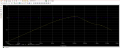
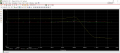
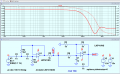
This is what LTSpice shows for the two sections of the first circuit
E
Please check my circuit for any layout errors

@ksnclaksnc
Corrected 'in' for 2nd stage.

EG57_ 1439.png
 
Last edited:

MrAl

Joined Jun 17, 2014
13,859
Hi k,
This is what LTSpice shows for the two sections of the first circuit
E
Please check my circuit for any layout errors
View attachment 314125
Hi Eric,

When you separate the two you have to keep R5 at the input to the second section. It is not needed on the output of the first section anyway.
That means the input to the second section is actually at the left side of R5 as drawn in your drawing and when it connects to R6 and C3.
 
Top