Facebook
 Google
 GitHub
 Linkedin
Hi Eric,
Here are my results:
1. Disconnect R19 from the IC4A pin#7.
Connect the free end of R19 to +5V, the relay should operate.
If it operates OK, then reconnect R19 to pin#7 of the IC4A.
The relay toggled and white LED illuminated.
2. Check that IC4A have +5v on pins 5,2,1 & pin#3 is 0V
Disconnect the link from pin#3 of the 555, that connects to IC4A pin #4
Touching the free end of the link to +5V should switch the output pin#7 of the IC4A and operate the relay.
If it operates OK [ it may 'chatter' because of the crude way of touching the +5V with the link]
Pins 5, 2, 1 do have +5V and pin 3 has 0V. I disconnected the link from pin#3 of IC2, with the opposite end still connected to IC4A pin #4, and touched the free end of that link to +5V. Relay did not toggle.
3. Check that IC2 the 555 has +5V on pins 4,2,8 and that R16 & C5 are correct.
Touching pin#2 of the 555 to 0V should trigger the 555 and operate the relay.
Pins 4, 2, 8 do have +5V and R16 and C5 are correct. When I touched pin#2 of IC2 to 0V, LED2 (GREEN) illuminated but the relay did not toggle.
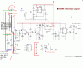
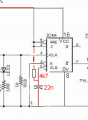
It looks to me like the problem is with IC4A. I have attached an image of my IC4A connections and a data sheet for it. Is there additional set-up that needs to be performed with IC4A?
Here are my results:
1. Disconnect R19 from the IC4A pin#7.
Connect the free end of R19 to +5V, the relay should operate.
If it operates OK, then reconnect R19 to pin#7 of the IC4A.
The relay toggled and white LED illuminated.
2. Check that IC4A have +5v on pins 5,2,1 & pin#3 is 0V
Disconnect the link from pin#3 of the 555, that connects to IC4A pin #4
Touching the free end of the link to +5V should switch the output pin#7 of the IC4A and operate the relay.
If it operates OK [ it may 'chatter' because of the crude way of touching the +5V with the link]
Pins 5, 2, 1 do have +5V and pin 3 has 0V. I disconnected the link from pin#3 of IC2, with the opposite end still connected to IC4A pin #4, and touched the free end of that link to +5V. Relay did not toggle.
3. Check that IC2 the 555 has +5V on pins 4,2,8 and that R16 & C5 are correct.
Touching pin#2 of the 555 to 0V should trigger the 555 and operate the relay.
Pins 4, 2, 8 do have +5V and R16 and C5 are correct. When I touched pin#2 of IC2 to 0V, LED2 (GREEN) illuminated but the relay did not toggle.
It looks to me like the problem is with IC4A. I have attached an image of my IC4A connections and a data sheet for it. Is there additional set-up that needs to be performed with IC4A?
Attachments
-
 188.2 KB Views: 6
 -
589.2 KB Views: 2