automatic doorbell

crutschow

Joined Mar 14, 2008
34,281
The 7555 is a CMOS version of the original 555 which uses BJT transistors. It should work in your circuit.

Note that there appears to be an error in that circuit. I think there should be a dot where the pin 6 connection crosses the pin 2 connection to indicated they should be connected together. Also, that circuit is not the typical astable multivibrator circuit for a 555 as seen here.
 

Thread Starter

rijoe.mathew

Joined Sep 21, 2014
42
now i replaced the original circuit 7555 with this circuit where R1=600 ohms,R2=18 kilo ohms, and C=.001uF.Is there any problem with the connections of LM324.Please advise how to identify the emitter of BC337 and BC327.its seems like the two transistor are heating up when i connect the input.please advice.is the any polarity for ultrasonic transducers
 

Attachments

ian field

Joined Oct 27, 2012
6,536
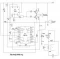
i have this circuit for my project.can i replace the 7555 with ne 555.what are the changes needed.please reply fast.

anyone please reply fast.i need this for tomorrow
You may find lower resistances are needed around the timing pins.

An undesirable feature of the bipolar 555, is the crossover point on the output stage - it has a tiny blip of crowbarring Vcc as one transistor hands over to the other, this can glitch other parts of the circuit.

You should put a 100nF cap as close as possible to the 555 supply pins, you should also have some bulk reservoir/bypass of at least 100uF for the whole circuit.
 

ericgibbs

Joined Jan 29, 2010
18,766
hi rijoe,
You cannot use that version of a 555 astable to drive an ultrasonic transducer.
It requires a 50:50 drive signal, at the same frequency as the original design. You will 'cook' the drive transistors!

Why have you changed the 555 circuit,?

Eric
 

ericgibbs

Joined Jan 29, 2010
18,766
hi rijoe,
Could you please post a link to the site where the circuit design was posted.?
The amplifier circuit as drawn will not work correctly.

E
 

Bernard

Joined Aug 7, 2008
5,784
Looks like there will be lots of shoot thru, ie , both transistors conducting at the same time = heat. Might consider connecting as emitter followers??
 

ian field

Joined Oct 27, 2012
6,536
hi rijoe,
You cannot use that version of a 555 astable to drive an ultrasonic transducer.
It requires a 50:50 drive signal, at the same frequency as the original design. You will 'cook' the drive transistors!


Eric
Are you saying you can't get 50:50 from a bipolar 555?!

With a couple of steering diodes and a pot you can adjust the duty cycle from about 5% to about 95%.

The best way to get accurate 50:50 is ignore pin 7 and take the timing resistor from pin 3 - this also saves the current limiting resistor from pin 7 to Vcc.
 

ericgibbs

Joined Jan 29, 2010
18,766
Are you saying you can't get 50:50 from a bipolar 555?!
No, I did not say that.
I said a version where the Output is connected to the timing components will give a 50:50 pulse period, of course pin3 is used as the output.
Why add diodes etc, when a simple solution already exists.?
Which will not give an exact 50:50 period anyway.

The circuit the OP is using is driving a resonant ultrasonic transducer, so a closer 50:50 will give a better result.

E
 

ericgibbs

Joined Jan 29, 2010
18,766
hi,
I have posted a comment on his web site asking him if has actually built and tested this circuit, as it will not work as drawn.
If I get a response I will let you know.

E
 
Top