
 Facebook
 Google
 GitHub
 Linkedin
Hi,
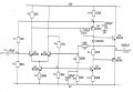
I have a pre-designed audio power amplifier to analyse and test. The circuit is attached.
I have got several values but during test some of them were not quite right.
My results
__________
differential (input) stage of about (-) 65.2 - that is for Q1
second stage gain of about 1224 - that is for Q4
feedback ratio, about 1/25 i.i 0.04
Overall gain of about 26
Input impedance of about 4.4KΩ
Output impedance of less that 1Ω
Low frequency limit of about 32Hz due to C2
High frequency limit of about 133kHz due to C3
at the output stage, we assume a load of 8Ω
Maximum operational output voltage was about 3V peak (positive)
which gave me an operational power delivered of about 0.56W
Power supply is about 1W
so effieciency gives me about 56%
The maximum power dissipated at each output transistor was about 0.51W
So heatsink not really needed.
TESTING
________
When testing my amplifier, The low and high frequencies limits were not right. I got about 25Hz and 4MHz for low and high frequency limits.
Can you please help me check my results. Especially for high and low frequency limits, and also power analysis?
I have a pre-designed audio power amplifier to analyse and test. The circuit is attached.
I have got several values but during test some of them were not quite right.
My results
__________
differential (input) stage of about (-) 65.2 - that is for Q1
second stage gain of about 1224 - that is for Q4
feedback ratio, about 1/25 i.i 0.04
Overall gain of about 26
Input impedance of about 4.4KΩ
Output impedance of less that 1Ω
Low frequency limit of about 32Hz due to C2
High frequency limit of about 133kHz due to C3
at the output stage, we assume a load of 8Ω
Maximum operational output voltage was about 3V peak (positive)
which gave me an operational power delivered of about 0.56W
Power supply is about 1W
so effieciency gives me about 56%
The maximum power dissipated at each output transistor was about 0.51W
So heatsink not really needed.
TESTING
________
When testing my amplifier, The low and high frequencies limits were not right. I got about 25Hz and 4MHz for low and high frequency limits.
Can you please help me check my results. Especially for high and low frequency limits, and also power analysis?
Attachments
-
 103.2 KB Views: 70






