Facebook
 Google
 GitHub
 Linkedin
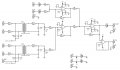
I want to make a new board for my organ and i have some doubts.
Does the line out look ok? Or should i get the signal from U2B pin 7 and feed it into U2B pin 2?
Also, the resistor and cap of the line out are ok?
Obs: the inputs of the transformers are differential signal from DACs. This i know it works.
Does the line out look ok? Or should i get the signal from U2B pin 7 and feed it into U2B pin 2?
Also, the resistor and cap of the line out are ok?
Obs: the inputs of the transformers are differential signal from DACs. This i know it works.
Attachments
-
96.1 KB Views: 23