 Facebook
 Google
 GitHub
 Linkedin
Hey guys,
I was designing an audio amplifier in my own time to enhance my electronics skills and I am having issues with the transistor part of the circuit. The specs are as follows:
Designing it with a +VCC with 0V supply
Frequency Range 20Hz - 20Khz
In-Band Sensitivity of 2V/mV maximum input of Plus-minus 15mV
In-Band input impedance will be 50k with the output load of a minimum of 2K
The power output is 20W RMS to an 8 Ohm speaker with less than 1% THD
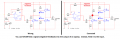
I have calculated the gain for each op-amp, I am using three LM741 op-amps, I know the gain bandwidth is 1Mhz thus all the op-amps will be 2000. I have calculated the resistors and capacitors.
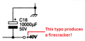
I'll attach my circuit but as from my research, I need the transistor set up the same as the second picture with additional supply. It will be an AB amplifier btw.
I am struggling to figure out how I am supposed to calculate the values for the transistor section.
I would appreciate some assistance, please.
Thanks

Second image wont load, please see the Class AB Amplifier Driver Stage from the link:
https://www.electronics-tutorials.ws/amplifier/class-ab-amplifier.html
I was designing an audio amplifier in my own time to enhance my electronics skills and I am having issues with the transistor part of the circuit. The specs are as follows:
Designing it with a +VCC with 0V supply
Frequency Range 20Hz - 20Khz
In-Band Sensitivity of 2V/mV maximum input of Plus-minus 15mV
In-Band input impedance will be 50k with the output load of a minimum of 2K
The power output is 20W RMS to an 8 Ohm speaker with less than 1% THD
I have calculated the gain for each op-amp, I am using three LM741 op-amps, I know the gain bandwidth is 1Mhz thus all the op-amps will be 2000. I have calculated the resistors and capacitors.
I'll attach my circuit but as from my research, I need the transistor set up the same as the second picture with additional supply. It will be an AB amplifier btw.
I am struggling to figure out how I am supposed to calculate the values for the transistor section.
I would appreciate some assistance, please.
Thanks
Second image wont load, please see the Class AB Amplifier Driver Stage from the link:
https://www.electronics-tutorials.ws/amplifier/class-ab-amplifier.html
Attachments
-
 9.4 KB Views: 12


")


