Nice shop ... I concur on the large screen monitor.
Nice VTVM I see. I haven't seen either of those VTVMs in many a year, or the HP oscillator.
Anyway, attached are the modifications to the schematic I've done so far .... as I work through each of the circuits. Can you provide some pics of that beast, front, back, top, bottom ... so I can peek at it when I have a question.
I appreciate it. the -161125JJ is the modification date and my initials.
Right on, I have a bunch of pics when I get home ill post stuff from my lap top. I screw stuff up on Phone
Isolated preamp its ok problem is in the main amplifier gotta be power related or a really pissed mosfet
You can plug directly into the Power Amp In and feed your audio just to the power amp. Then you have used the "injection" method" so the problem lies between the Power Amp IN and the output of the power amp. An actual block diagram would have cut your time down considerably.
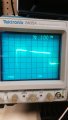
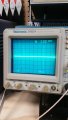
1khz sine is from preamp out = good
120 hz square wave with negative slope backed to input when tuner switch connected to amp =no go
1khz squiggly square wave (probe is grounded) is at- ins send and return.
yellow trace is final output across 8ohm dummy load resistor before volume applied (idle)
disregard others (clicked too many pics)
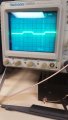
On your picture ending in 2803, the TDS 2002 scope, is that a high frequency imposed on that square wave?
When taking pictures, you can use a hood of some sorts to reduce the reflection of the overhead light and turn the beam intensity down. Your picture will be clear ....
So, with this new information, where do you suspect the problem originates?
Where was your input square wave and where did you measure the wave?
Im not injecting a square wave lol just the 1khz. i have more pics and vids for you fighting my phone and air droid says files are too large .doing a work around my friend .The best is yet to come. I replaced q3 it protects signal path from dc voltage no change my next thoughts are zeners. Z3 Z4 i think could be shortesd to ground the 120hz noise is the tell maybe ill show you the high freq at amp in soon bare with me
I wouldn't worry too much about that slope with the squarewave input. The simulation was done with Chan B as the input, and the outputs measured at each block ... All variable resistors were set at 50%
Here are the simulation results for the circuits I have completed ....
 Facebook
 Google
 GitHub
 Linkedin