Hi guys, so sorry I was meant to write to you a few days ago but life the universe and everything got in the way plus I was doing the boy's party. Okay, holes are drilled and I have one pot fitted to the board but the other hole needs my attention (the pot has a fan shaped piece at the top and the spike is still not sticking through so I need to thin it and no joy with the spade bit) so I'm treating myself to a VERY early birthday pressie of some chisels (along with the jig saw and spade drill bits and wheel drill bits I bought as well last month lol!). I haven't been able to progress on this bit but the "fridge" is finished, the door just needs planing straight and extra holes for the second hinge to be drilled. I'm going to do that Tuesday morning, I need a day off as the bump needs attention and I have a scan booked tomorrow. I have also drilled the hole for the kitchen tap so we're really getting there. You should hear from me by Wednesday. Hope you guys are well.
PS the knob looks great on the board, it just doesn't lay as flat as I'd like but I suspect this is the "chuck" and I'm not sure how to rectify it.
Yes I did and I drilled a small hole but even with that it needs a little thinning. I'm just leery as I don't want to drill through the wood, I think using a chisel will be safer.
Well I suppose you can only delay the inevitable. Hole drilled too big now having to fix it. A pretty easy fix, just need a washer bigger than said hole. Not panicking, just want to get finished now, got to say it's been rather frustrating, I'm kinda figuring it out as I'm going along.
Drilled hole too big but found a washer that has worked wonderfully, the pot spike was just through enough to get a couple of turns of the nut but then I used a ratchet to get a few more turns in so that's really sealed the deal and that pot ain't going nowhere! So now I feel like I'm making headway at last. I've turned my attention to a couple of other parts to this project (fridge) and that involved getting more screws and supplies (yikes) so that's kept me busy. Tomorrow my son and husband are out most of the day so my plan is to knuckle down with this oven part, I want to also start building the kitchen oh and the clips to hold the "element" have arrived so that's cool and the guy who was making the microwave and dishwasher elements has sent them over. So it's just a case of getting everything hooked up! :-D I'll probably write you tomorrow, if I'm struggling or something but I thiiiiink (fingers crossed) I've got enough savvy to be able to figure it out now. I'll just take it slow and go one piece at a time
Confusion reigns, my error in not labeling pg. 4,#70 Front View as it started to be & drilling should be from pg. 6, #105 so that viewing from the front the SW on left & pot on right; as drilled seems that they are reversed. Keep it this way or is it possible to reverse positions of SW & pot ?
Keep it this way please Bernard when facing the front the clicking pot (the black one, apologies for using the wrong term) is on the left and the silver on the right, as the black one that clicks is for the on and off of the light it's in the right place and would make sense to be there as you'd turn that one first. Hope that's okay.
I hope that this is clear enough. R2 can be 1/4 W or 1/2 W, 9.1k or temp. use 50k pot to set a value. The HS, heat sink can be placed anywhere & remember that a mounting hole needs to be drilled in it. Trim mica washer to fit in HS, goes between Q1 & HS. Assuming that HS existing hole is threaded to fit provided machine screw. " They" said that it is easy to cut the TS in half. I've never had one. It can remain as one piece, up to you to arrange connections.
OMG it's like the light has gone on literally, this is BRILLIANT Bernard and so clear now, thank you so much (I also think it's helped that I've learnt quite a lot as we've gone on).
Assuming the 50K pot is the silver one (R1) as you're calling the other one an SW.
Can confirm chock blocks (TSs) are easy to cut, HS has pre-drilled hole as does mica.
So my only question now is "What is Q1 please?" I couldn't work out if it's either a single part of a TS or something else entirely.
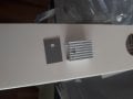
By the way: The HS comes with a small piece of foam, I remember you said the HS needs mounting, does it need a separate bit of wood underneath it or is that what the foam is for? Judging by the size of the screw I assume this has to go fin side down so it looks like a U?
I attach a pic of the HS for clarity.
'Hope this will help. Q1 is the transistor. R1 is 5k pot. R2 is 1/4 W,. 9.1k resistor or temporary use of 50k pot. Black " foam" from HS pkg. is insulator, goes between Q1 & HS. Note that Q1 is mounted in the reverse direction from normal but there is still ample heat path as shown & allows for the drilling of a hole for mounting to wood panel. Make sense??
Oh actually @Bernard one last question I have something here that's a piece of see through plastic, I thought this was the mica. Maybe I got it as the insulator for the heat sink? Does that mean I don't need it as I have the foam, the foam came with the heat sink. Can't really take a pic as it's see through so here is the part from mouser https://www.mouser.co.uk/ProductDetail/534-4724
Should I use this like their picture shows or is the foam I have enough, the foam came with the heat sink but this was on your list of things for me to buy.
 Facebook
 Google
 GitHub
 Linkedin
") Hope you guys are well.
Hope you guys are well.