Atmega328 keeps resetting itself if I start PWM

Thread Starter

sumeryamaner

Joined May 29, 2017
114
In a project using an Atmega328, I am controlling two electric motors, two relays and a glow plug (RC model engine glow plug).
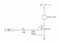
Attached you can find the circuit controlling the glow plug.
The circuit is being powered by a 2S LiPo battery (7.4 - 8.4 V). The controller part with the Atmega receives it's power from a 5V regulator (7805 or 2940).
Under these conditions the PWM value to drive the glow plug is about 15 (out of 255).
The main problem is, whenever I activate the glow plug PWM, the microcontroller resets itself.
I think this is due to decreasing input voltage of the 5V regulator.

What I have tried;
- BOD levels OFF, 1.8V, 2.7 V, 3.6(?) V --> didn't change anything

- Different values for the series resistor to the MOSFET gate. 75 ohms, 470 ohms, 1 k, 2.2k, and these with or without the 47k resistors to ground. If I use a 2.2k resistor, there is no problem. The circuit works as expected. But the MOSFET gets too hot. In this case the required PWM value to drive the glow plug is also higher. This leads me to think that the higher resistor value does not allow the MOSFET to conduct fully. This in turn prevents sudden drop in the supply voltage but this also leads to a higher voltage drop at the MOSFET heating it up.

- Different MOSFETs. Logic level MOSFET IRL540N and regular MOSFET IRFZ44. IRFZ44 works better and cooler than the "logic level" counterpart.

- Starting with a PWM value of 1 and increasing it up to 15 in 500 millisecond periods. That means it takes about 7 seconds for the PWM signal to reach it's maximum value. Most of the time the microcontroller hangs or resets during this part of the code.

- If I do not connect the glow plug there is no reset or hang up. This finding strongly suggests that this is a power supply issue.

I have added a capacitor of 100 uF before the 5V regulator, a 100 uF capacitor after the 5V regulator, a 10 uF capacitor just at the VCC pin of the Atmega and a 10 uF capacitor just at the AVCC pin of the Atmega. I have used a fully charged 2S LiPo of 3500 mAh. The nominal current of a glow plug is about 3 - 4 Amps and I don't think that this current can collapse the voltage of a fully charged LiPo battery.

I am planning to run a last test. I will use a separate LiPo for the logic part of the circuit.

In the menatime I am open to any suggestions...

BTW there is a similar problem when I try to control the two motors using PWM but there are no problems with the relays (all of them have a similar MOSFET drive setup):

PS: I have done my best to describe the problem clearly but please feel free to ask if there are obscure points.
 

Attachments

MrSoftware

Joined Oct 29, 2013
2,188
I skimmed so forgive me if I missed a detail. The glow plug likely has a coil in it, which means it may have significant induction. Add a flyback diode across the glow plug.

If that doesn't do the trick, then scope the atmega voltage supply and see what's going on there. If nothing unusual is happening then scope the IO lines, maybe you're getting a spike somewhere.
 

Alec_t

Joined Sep 17, 2013
14,280
The problem could be due to 'ground bounce', if any part of the ground return path of the micro is shared by a high current device such as the glow-plug. Do you have a 'star ground' arrangement to combat ground bounce?
 

Thread Starter

sumeryamaner

Joined May 29, 2017
114
I skimmed so forgive me if I missed a detail. The glow plug likely has a coil in it, which means it may have significant induction. Add a flyback diode across the glow plug.

If that doesn't do the trick, then scope the atmega voltage supply and see what's going on there. If nothing unusual is happening then scope the IO lines, maybe you're getting a spike somewhere.
You can be sure that the inductance of our glow plug coils are negligible and the same problem exists with the electric motors which have flyback diodes.
 

Thread Starter

sumeryamaner

Joined May 29, 2017
114
The problem could be due to 'ground bounce', if any part of the ground return path of the micro is shared by a high current device such as the glow-plug. Do you have a 'star ground' arrangement to combat ground bounce?
I have a relatively wide ground track (not a star ground arrangement) and today I will solder an extra cable from the microcontroller ground to the battery ground. But I don't think this is the reason...
 

BobaMosfet

Joined Jul 1, 2009
2,110
Have you put an oscilloscope on your Vcc rail to see what it does when this happens? If it drops, it's because you're drawing too much current, and your power-supply is collapsing (or regulator), and so voltage drops.

What is your PWM frequency? The higher it is, the more current is being drawn, because you get closer to simply being equivalent to an ON, rather than a pulse.
 

BobTPH

Joined Jun 5, 2013
8,804
I have a relatively wide ground track (not a star ground arrangement) and today I will solder an extra cable from the microcontroller ground to the battery ground. But I don't think this is the reason...
What you want is separate tracks from the grouuding point to the uP and the glow plug. Both should emanate from the neg lead of a tank cap where power comes into the board.

Bob
 

Thread Starter

sumeryamaner

Joined May 29, 2017
114
What you want is separate tracks from the grouuding point to the uP and the glow plug. Both should emanate from the neg lead of a tank cap where power comes into the board.

Bob
I have soldered a thick wire from the GND connection of the Atmega to the point where I have soldered the negative pin of the battery. And I soldered an additional thick wire from the GND connection of the glow plug driver MOSFET to the point where I soldered the negative pin of the battery. This didn't change anythnig.
The microcontroller kept resetting or locking up as soon as the PWM signal was ON.

Have you put an oscilloscope on your Vcc rail to see what it does when this happens? If it drops, it's because you're drawing too much current, and your power-supply is collapsing (or regulator), and so voltage drops.

What is your PWM frequency? The higher it is, the more current is being drawn, because you get closer to simply being equivalent to an ON, rather than a pulse.
I haven't scope the rails yet. I am not sure whether my hobby oscilloscope would show anything in this case but I will try it.

I am using Arduino IDE to write and compile my code. So I am using AnalogWrite function most of the time. The standart Arduino AnalogWrite function gives 980 Hz at this pin I am using for PWM output.

A last update:

I have disconnected the microcontroller power from the supply of the peripheral devices. I connected another 2S LiPo battery to the LM2940 5V regulator. That means my control logic and devices with high power demand have now separate power supplies with a common GND. The problem persisted!

Then I replaced the 470 ohm gate resistors with 1k ones. Now everything works fine.

But why???
 
I don't know, but this part of your diagnostics seems like the clue...
- Different values for the series resistor to the MOSFET gate. 75 ohms, 470 ohms, 1 k, 2.2k, and these with or without the 47k resistors to ground. If I use a 2.2k resistor, there is no problem. The circuit works as expected. But the MOSFET gets too hot. In this case the required PWM value to drive the glow plug is also higher. This leads me to think that the higher resistor value does not allow the MOSFET to conduct fully. This in turn prevents sudden drop in the supply voltage but this also leads to a higher voltage drop at the MOSFET heating it up.
A while ago I had a thread where I was inquiring about R1 and R2 using an IRL540, so, to raise this without exacerbating my ignorance, I will pose the question to you...

How are you choosing the values of R1 and R2?

R2 is easiest to understand because you want the gate at GND if the I/O port is high impedance or floating or whatever the accurate term is - at least that is my understanding. For me, 10K works fine in the few applications that I have used.

Now, how to calculate R1, knowing that you only need, what 2V to the gate of an IRL540 to have it as on as it gets?

I have a good app note about that somewhere, but for discussion, see https://forum.digikey.com/t/why-put-a-resistor-in-series-with-the-gate-of-a-fet/1009

But, while that note explains the purpose of the series resistor, it does not explain how to calculate the value. How are you calculating the value of R2 R1?

If you remove R1 entirely, what happens? If you use R1=1K, R2=10K what happens?

I ask because I want to learn.
 
Last edited:

Thread Starter

sumeryamaner

Joined May 29, 2017
114
I don't know, but this part of your diagnostics seems like the clue...


A while ago I had a thread where I was inquiring about R1 and R2 using an IRL540, so, to raise this without exacerbating my ignorance, I will pose the question to you...

How are you choosing the values of R1 and R2?

R2 is easiest to understand because you want the gate at GND if the I/O port is high impedance or floating or whatever the accurate term is - at least that is my understanding. For me, 10K works fine in the few applications that I have used.

Now, how to calculate R1, knowing that you only need, what 2V to the gate of an IRL540 to have it as on as it gets?

I have a good app note about that somewhere, but for discussion, see https://forum.digikey.com/t/why-put-a-resistor-in-series-with-the-gate-of-a-fet/1009

But, while that note explains the purpose of the series resistor, it does not explain how to calculate the value. How are you calculating the value of R2 R1?

If you remove R1 entirely, what happens? If you use R1=1K, R2=10K what happens?

I ask because I want to learn.
First of all, a logic level MOSFET like IRL540N may need 2 Volts to start conducting but it needs more than 4 Volts to fully conduct.
Interestingly in my setup if I replace the IRL540N with a IRFZ44 with the same resistor values, I am getting a way higher current output. Let me explain it better: For example with an IRL540N I need about 50 (/255) PWM to light up the glow plug and with the same setting with an IRFZ44 the glow plug burns out! I don't have any explanation for this.

Now the case with the R1...

There is a gate capacitor which must be charged. It is in a picofarad range. But at the beginning it is discharged and if we apply 5V to it it will draw a high current for a very short time. So I assume that I am connecting the MCU output directly to GND via R1. To limit the current to 20 mA I need a resistor of about 250 ohms. So I decided to use 470 ohms. In my opinion, the value of the resistor is important only in high frequency PWM applications. But with a PWM frequency of 980 Hz I should be able to use any value unless it is 100 kohm range or higher.

Please bear in mind that I am not a professional in this field. :)
 

BobTPH

Joined Jun 5, 2013
8,804
The thing that changes when you change the gate resistor is the turn on and turn off times. This points to inductance as the problem since fast transition times will create greater voltage spikes.

You said you tried adding separate ground wires, but what about power, they should also be star connected.

Bob
 
First of all, a logic level MOSFET like IRL540N may need 2 Volts to start conducting but it needs more than 4 Volts to fully conduct.
Interestingly in my setup if I replace the IRL540N with a IRFZ44 with the same resistor values, I am getting a way higher current output. Let me explain it better: For example with an IRL540N I need about 50 (/255) PWM to light up the glow plug and with the same setting with an IRFZ44 the glow plug burns out! I don't have any explanation for this.

Now the case with the R1...

There is a gate capacitor which must be charged. It is in a picofarad range. But at the beginning it is discharged and if we apply 5V to it it will draw a high current for a very short time. So I assume that I am connecting the MCU output directly to GND via R1. To limit the current to 20 mA I need a resistor of about 250 ohms. So I decided to use 470 ohms. In my opinion, the value of the resistor is important only in high frequency PWM applications. But with a PWM frequency of 980 Hz I should be able to use any value unless it is 100 kohm range or higher.

Please bear in mind that I am not a professional in this field. :)
I am bearing that in mind...please bear in mind that I feel pretty strongly that I know less about it than you :)

You are definitely correct about "...Volts to start conducting but it needs more than 4 Volts to fully conduct.", see I told you that I knew less than you. Just reading here https://assets.nexperia.com/documents/application-note/AN90001.pdf about Vgs(th) and ..."Depending on whether a device is logic-level or standard-level, a MOSFET can be considered fully-enhanced (or fully on) when the VGS is 5 V or10 V respectively. By this point the MOSFET has achieved its rated RDS(ON)."

Thanks for responding with regard with how you calculated R1...I bet someone will tell you why it is not that easy, but I am learning...may not solve your problem though ;)
 

Thread Starter

sumeryamaner

Joined May 29, 2017
114
The thing that changes when you change the gate resistor is the turn on and turn off times. This points to inductance as the problem since fast transition times will create greater voltage spikes.

You said you tried adding separate ground wires, but what about power, they should also be star connected.

Bob
I tried two fully separate power supplies... So there shouldn't be a power wire issue im my opinion.
 

Thread Starter

sumeryamaner

Joined May 29, 2017
114
I am bearing that in mind...please bear in mind that I feel pretty strongly that I know less about it than you :)

You are definitely correct about "...Volts to start conducting but it needs more than 4 Volts to fully conduct.", see I told you that I knew less than you. Just reading here https://assets.nexperia.com/documents/application-note/AN90001.pdf about Vgs(th) and ..."Depending on whether a device is logic-level or standard-level, a MOSFET can be considered fully-enhanced (or fully on) when the VGS is 5 V or10 V respectively. By this point the MOSFET has achieved its rated RDS(ON)."

Thanks for responding with regard with how you calculated R1...I bet someone will tell you why it is not that easy, but I am learning...may not solve your problem though ;)
I'm learning too. I'm an amateur. But I have designed and built many projects for my RC aircraft. For example I have an on board glow driver and a kill switch for gasoline engine. In the former I am using exact the same setup with R1 1k and R2 22k. In the latter I am not using PWM and switch the MOSFET directly ON and OFF. But the gate is isolated with an optocoupler. In these two devices I havenever experienced any problems.
This circuit is a more complex one. This is the second prototype PCB. In the first I didn't include R2's. And R1's were 2.2 k. There is a thread in AAC about it. If the microcontroller was not in place or I was testing part of the code with the PWM outputs in high impedance state the accumulating static charge led to unexpected switching ON of the motors. So I decided to put the pull down resistors and in order to prevent the decrease of the gate voltages, I decided to reduce the value of the R1's to 470 ohms. But it didn't work.
 

danadak

Joined Mar 10, 2018
4,057
Not all capacitors of the same C value are equal in their performance capability,
ESR in particular -


Read datasheet for ESR behavior.

Also when using bulks add a .1 uF ceramic in parallel, as its HF ESR helps
alleviate the rising bulk ESR problem at HF. Some also add a .01 ceramic
as well.

Lastly ferrite beads on some signal lines can be helpful. Especially lines with
high valued Z, like unterminated CMOS inputs or terminated by relatively high
valued pullups. A few K OK, 10's of K recipe for trouble. This helps minimize
coupling of transients into pins.


Regards, Dana.
 
There is a thread in AAC about it. If the microcontroller was not in place or I was testing part of the code with the PWM outputs in high impedance state the accumulating static charge led to unexpected switching ON of the motors. So I decided to put the pull down resistors and in order to prevent the decrease of the gate voltages, I decided to reduce the value of the R1's to 470 ohms. But it didn't work.
I remember https://forum.allaboutcircuits.com/...lem-with-atmega328.157574/page-2#post-1366363 you were "bedeviled".
 

MrSoftware

Joined Oct 29, 2013
2,188
Depending on the frequency, with a large gate resistor your fet might not be turning all the way on. You can scope it and see if the gate voltage gets high enough to turn all the way on. Did you try a flyback diode with the smaller gate resistor just to see if it resolves the problem?

The gate resistor on the fet should just be there to stop ringing, I believe the larger gate resistor is masking the problem and not actually curing it.
 
Top