Facebook
 Google
 GitHub
 Linkedin
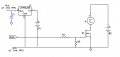
If we are talking about a very high current collapsing the battery voltage as a cause of the reset, I can say "yes".Question, is the mosfet completely isolated from the MCU circuit?
Atmega328 keeps resetting itself if I start PWM
- Thread starter sumeryamaner
- Start date
")