ATmega reset by using transformer power supply

ATmega reset by using transformer power supply!!! is any problem with my design ?!?!!!

  • Power Supply

    Votes: 0 0.0%
  • ATMEGA

    Votes: 0 0.0%
  • LM2596

    Votes: 0 0.0%

  • Total voters
    0

ebeowulf17

Joined Aug 12, 2014
3,307
Another thought, make sure the -Ve lead from the motors goes directly to the bridge -Ve to prevent the motor current running through the processor regulator leads. It is always a good idea to keep the high currents away from the controller circuit. layout is important and bad layout of a switch mode supply can cause real troubles. have a look at the app notes
Yeah, that's a good thought. I had an especially tricky issue of my own several years ago that turned out to be a problem with the local "ground" getting driven too high by transient induced currents (the "ground" wires were woefully inadequate, thankfully not my design.)

Perhaps the motor start current is pushing some portion of the "ground" / DC common high towards the +5 or +24 lines.
 

Thread Starter

hossein ghapanchi zadeh

Joined Nov 7, 2017
13
Sorry for my delay to reply.I connect directly motors power to the bridge (-V and +V) and add a diode (1N4007) to separate Reg input and added 2200uF capacitor for Reg. still same problem happened.
I moved 2200uF cap to out put of reg but nothing change.
I added 1000uF close to the Vcc of MCU and everything works correctly even when I move all motors with maximum load !!!!
The issue as you and ebeowulf17 said is the low current!
 

Thread Starter

hossein ghapanchi zadeh

Joined Nov 7, 2017
13
Yeah, that's a good thought. I had an especially tricky issue of my own several years ago that turned out to be a problem with the local "ground" getting driven too high by transient induced currents (the "ground" wires were woefully inadequate, thankfully not my design.)

Perhaps the motor start current is pushing some portion of the "ground" / DC common high towards the +5 or +24 lines.
yes. I do believe that its the issue .
do I need to use reverse bias diode for MCU and Reg ground? or any other idea?
 

ebeowulf17

Joined Aug 12, 2014
3,307
If the 1000uF cap gets the job done, why not use it? Or experiment with different values to see how low you can go before it gets unreliable again.

It's not at all unusual to use multiple caps right at the supply of an IC or microcontroller (0.1uF and 10uF together seems to be an especially common combo.) We don't have a complete schematic, so I'm still guessing, but I seem to remember that you had the 0.1uF, but nothing else at the microcontroller. Just add whatever caps you need there to make it stable and call it a day!

Sorry for my delay to reply.I connect directly motors power to the bridge (-V and +V) and add a diode (1N4007) to separate Reg input and added 2200uF capacitor for Reg. still same problem happened.
I moved 2200uF cap to out put of reg but nothing change.
I added 1000uF close to the Vcc of MCU and everything works correctly even when I move all motors with maximum load !!!!
The issue as you and ebeowulf17 said is the low current!
 

Thread Starter

hossein ghapanchi zadeh

Joined Nov 7, 2017
13
If the 1000uF cap gets the job done, why not use it? Or experiment with different values to see how low you can go before it gets unreliable again.

It's not at all unusual to use multiple caps right at the supply of an IC or microcontroller (0.1uF and 10uF together seems to be an especially common combo.) We don't have a complete schematic, so I'm still guessing, but I seem to remember that you had the 0.1uF, but nothing else at the microcontroller. Just add whatever caps you need there to make it stable and call it a day!
Thanks for your time you lead me in courrect way.
I'd like to know what is your opinion to isolate ground of MCU !!! do you have any suggestion for that ?
 

ebeowulf17

Joined Aug 12, 2014
3,307
Thanks for your time you lead me in courrect way.
I'd like to know what is your opinion to isolate ground of MCU !!! do you have any suggestion for that ?
I'm not sure - I'm still learning all this stuff too. I think a "Star Grounding" scheme would help, but I can't say for sure. There may be a lot of different things going on here, and it's all a little over my head. Sometimes I just have to go with the practical solution I find through experimentation, because theory doesn't always get me there. Nevertheless, understanding good practices is helpful, and I think star grounding is a good thing to learn about.

@MaxHeadRoom has shared some great documents with me on this subject, but I've lost track of them. He might have some helpful insights. He's a genius when it comes to motors, high voltage noise and grounding considerations, etc. You can also simply google "star grounding" and you should find lots of good resources.

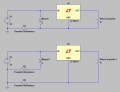
Here's my attempt at explaining part of the star grounding idea, and how it might apply in your situation. Take a look at these two simplified schematics:
star-ground_parasitic-resistance.png
In the top example, the grounds are joined together wherever it's convenient. This would work fine if the wires/traces involved had no resistance, impedance, or inductance to worry about. Unfortunately, in the real world there are parasitic components of all those things in every wire, trace, component, etc.

When the motors aren't running, everything is fine, and the ground behaves as expected for the 5V regulator and the microcontroller. However, when the motors are running, there's a large amount of current running through the wires, including the groud wires. Since the wires have a parasitic resistance, there's a voltage drop across the wires in proportion to its resistance value. This pushes the "ground" voltage at the regulator and microcontroller up to a higher voltage than it was before.

When the motors are running steadily, this will probably still work ok, because the voltage regulator will adjust its output to deliver 5V above what it thinks is ground, even though its ground is a little bit higher voltage than the "real" ground. However, when the motors start and stop, there are sudden changes in current, voltage drop, and apparent "ground" voltage as seen by the regulator and microcontroller. These sudden changes could potentially cause glitches or dropouts.

The high surges of current required when starting motors, along with the parasitic inductance of the wire, conspire to make things especially bad when first starting the motors.

In the lower example, each sub-circuit has its own separate path all the way back to one common grounding point - this common grounding point will vary depending on the situation, but it should be the place where the "ground" is most stable - whether it's the best connection you have to an earth-ground cable, a good chassis lug, the negative side of your main power supply. Whatever that point is, the key is to have all grounds run all the way back to this one point, not split off halfway down a wire.

The advantage here is that now, the parasitic resistance and inductance of the motor wires have no effect on the ground reference for the 5V regulator and the microcontroller. Voltages along the motor's "ground" wire might go all over the place when the motors start and stop, but the 5V circuit will always have its own, solid, reliable path all the way back to the ground.

Now, having said all that, I still have no idea if this is the real problem or real solution in your case. It's just one theory. Good luck!
 

Thread Starter

hossein ghapanchi zadeh

Joined Nov 7, 2017
13
I'm not sure - I'm still learning all this stuff too. I think a "Star Grounding" scheme would help, but I can't say for sure. There may be a lot of different things going on here, and it's all a little over my head. Sometimes I just have to go with the practical solution I find through experimentation, because theory doesn't always get me there. Nevertheless, understanding good practices is helpful, and I think star grounding is a good thing to learn about.

@MaxHeadRoom has shared some great documents with me on this subject, but I've lost track of them. He might have some helpful insights. He's a genius when it comes to motors, high voltage noise and grounding considerations, etc. You can also simply google "star grounding" and you should find lots of good resources.

Here's my attempt at explaining part of the star grounding idea, and how it might apply in your situation. Take a look at these two simplified schematics:
View attachment 141079
In the top example, the grounds are joined together wherever it's convenient. This would work fine if the wires/traces involved had no resistance, impedance, or inductance to worry about. Unfortunately, in the real world there are parasitic components of all those things in every wire, trace, component, etc.

When the motors aren't running, everything is fine, and the ground behaves as expected for the 5V regulator and the microcontroller. However, when the motors are running, there's a large amount of current running through the wires, including the groud wires. Since the wires have a parasitic resistance, there's a voltage drop across the wires in proportion to its resistance value. This pushes the "ground" voltage at the regulator and microcontroller up to a higher voltage than it was before.

When the motors are running steadily, this will probably still work ok, because the voltage regulator will adjust its output to deliver 5V above what it thinks is ground, even though its ground is a little bit higher voltage than the "real" ground. However, when the motors start and stop, there are sudden changes in current, voltage drop, and apparent "ground" voltage as seen by the regulator and microcontroller. These sudden changes could potentially cause glitches or dropouts.

The high surges of current required when starting motors, along with the parasitic inductance of the wire, conspire to make things especially bad when first starting the motors.

In the lower example, each sub-circuit has its own separate path all the way back to one common grounding point - this common grounding point will vary depending on the situation, but it should be the place where the "ground" is most stable - whether it's the best connection you have to an earth-ground cable, a good chassis lug, the negative side of your main power supply. Whatever that point is, the key is to have all grounds run all the way back to this one point, not split off halfway down a wire.

The advantage here is that now, the parasitic resistance and inductance of the motor wires have no effect on the ground reference for the 5V regulator and the microcontroller. Voltages along the motor's "ground" wire might go all over the place when the motors start and stop, but the 5V circuit will always have its own, solid, reliable path all the way back to the ground.

Now, having said all that, I still have no idea if this is the real problem or real solution in your case. It's just one theory. Good luck!
I got it. I will try to use it. Thanks to sharing information
 
Top